AS5045 AB austriamicrosystems, AS5045 AB Datasheet - Page 17
AS5045 AB
Manufacturer Part Number
AS5045 AB
Description
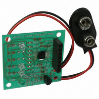
BOARD ADAPTER AS5045
Manufacturer
austriamicrosystems
Specifications of AS5045 AB
Sensor Type
Magnetic, Rotary Position
Sensing Range
360°
Interface
Serial
Voltage - Supply
9V
Embedded
No
Utilized Ic / Part
AS5045
Lead Free Status / RoHS Status
Lead free by exemption / RoHS compliant by exemption
Sensitivity
-


AS5045
Data Sheet
9.1 Changing the PWM Frequency
The PWM frequency of the AS5045 can be divided by two by setting a bit (PWMhalfEN) in the OTP register (see
chapter 11). With PWMhalfEN = 0 the PWM timing is as shown in Table 6:
Table 6. PWM Signal Parameters (default mode)
When PWMhalfEN = 1, the PWM timing is as shown in Table 7:
Table 7. PWM Signal Parameters with Half Frequency (OTP option)
10 Analog Output
An analog output can be generated by averaging the PWM signal, using an external active or passive low pass filter.
The analog output voltage is proportional to the angle: 0°= 0V; 360° = VDD5V.
Using this method, the AS5045 can be used as direct replacement of potentiometers.
Figure 9. Simple 2
Figure 9 shows an example of a simple passive low pass filter to generate the analog output.
R1, R2 ≥ 4k7
R1 should be ≥4k7 to avoid loading of the PWM output. Larger values of Rx and Cx will provide better filtering and
less ripple, but will also slow down the response time.
www.austriamicrosystems.com
PWM frequency
MIN pulse width
MAX pulse width
PWM frequency
MIN pulse width
MAX pulse width
Parameter
Parameter
C1, C2 ≥ 1µF / 6V
nd
Order Passive RC Low Pass Filter
Symbol
Symbol
PW
PW
PW
PW
f
f
PWM
PWM
MAX
MAX
MIN
MIN
Revision 1.7
4096
8192
Typ
Typ
244
122
1
2
Unit
Unit
Hz
Hz
µs
µs
µs
µs
- Position 4095d
- Angle 359.91 deg
- Position 4095d
- Angle 359.91 deg
Signal period: 4097µs
- Position 0d
- Angle 0 deg
Signal period: 8194µs
- Position 0d
- Angle 0 deg
Note
Note
17 – 33
Related parts for AS5045 AB
Image
Part Number
Description
Manufacturer
Datasheet
Request
R

Part Number:
Description:
IC ENCODER PROG 12-BIT 16-SSOP
Manufacturer:
austriamicrosystems
Datasheet:

Part Number:
Description:
BOARD DEMO AS5045
Manufacturer:
austriamicrosystems
Datasheet:
Part Number:
Description:
IC ENCODER PROG 12-BIT 16-SSOP
Manufacturer:
austriamicrosystems
Datasheet:
Part Number:
Description:
12-bit Programmable Magnetic Rotary Encoder
Manufacturer:
austriamicrosystems
Datasheet:
Part Number:
Description:
BOARD PROGRAM AS5040
Manufacturer:
austriamicrosystems
Datasheet:
Part Number:
Description:
IC SWITCH QUAD SPST 14-TSSOP
Manufacturer:
austriamicrosystems
Datasheet:
Part Number:
Description:
IC SWITCH QUAD SPST 14-TSSOP
Manufacturer:
austriamicrosystems
Datasheet:
Part Number:
Description:
IC AMP AUDIO MONO 1.8W 10-MSOP
Manufacturer:
austriamicrosystems
Datasheet:
Part Number:
Description:
IC AMP AUDIO MONO 1.8W 10-MSOP
Manufacturer:
austriamicrosystems
Datasheet:
Part Number:
Description:
IC AMP AUDIO MONO 1.8W 10-MSOP
Manufacturer:
austriamicrosystems
Datasheet:
Part Number:
Description:
IC AMP AUD 1.8W 3DB GAIN 10-MSOP
Manufacturer:
austriamicrosystems
Datasheet:
Part Number:
Description:
IC DRIVER LED 8-DIGIT 24-SOIC
Manufacturer:
austriamicrosystems
Datasheet:
Part Number:
Description:
IC DRIVER LED 8-DIGIT 24-SOIC
Manufacturer:
austriamicrosystems
Datasheet:
Part Number:
Description:
IC, LINE/SPEAKER PHONE CIRCUIT, SOIC-28
Manufacturer:
austriamicrosystems
Datasheet:
Part Number:
Description:
IC MULTI-STANDARD CMOS TELEPHONE SOIC-28
Manufacturer:
austriamicrosystems
Datasheet: