AD9433/PCB Analog Devices Inc, AD9433/PCB Datasheet - Page 17
AD9433/PCB
Manufacturer Part Number
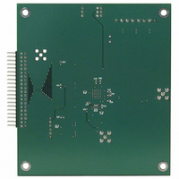
AD9433/PCB
Description
BOARD EVAL FOR AD9433
Manufacturer
Analog Devices Inc
Datasheet
1.AD9433BSVZ-105.pdf
(20 pages)
Specifications of AD9433/PCB
Rohs Status
RoHS non-compliant


THEORY OF OPERATION
The AD9433 is a 12-bit pipeline converter that uses a switched-
capacitor architecture. Optimized for high speed, this converter
provides flat dynamic performance up to and beyond the
Nyquist limit. DNL transitional errors are calibrated at final test
to a typical accuracy of 0.25 LSB or less.
ENCODE INPUT
Any high speed ADC is extremely sensitive to the quality of the
sampling clock provided by the user. A track-and-hold circuit is
essentially a mixer, and any noise, distortion, or timing jitter on
the clock is combined with the desired signal at the ADC output.
For this reason, considerable care has been taken in the design
of the encode input of the AD9433, and the user is advised to
give commensurate thought to the clock source.
The AD9433 has an internal clock duty cycle stabilization
circuit that locks to the rising edge of ENCODE (falling edge
of ENCODE if driven differentially) and optimizes timing
internally. This allows for a wide range of input duty cycles at
the input without degrading performance. Jitter in the rising
edge of the input is still of paramount concern and is not
reduced by the internal stabilization circuit. This circuit is
always on and cannot be disabled by the user.
The ENCODE and ENCODE inputs are internally biased
to 3.75 V (nominal) and support either differential or single-
ended signals. For best dynamic performance, a differential
signal is recommended. Good performance is obtained using
an MC10EL16 translator in the circuit to directly drive the
encode inputs (see
Often, the cleanest clock source is a crystal oscillator producing
a pure, single-ended sine wave. In this configuration, or with
any roughly symmetrical, single-ended clock source, the signal
can be ac-coupled to the encode input. To minimize jitter, the
signal amplitude should be maximized within the input range
described in Table 7. The 12 kΩ resistors to ground at each of
the inputs, in parallel with the internal bias resistors, set the
common-mode voltage to approximately 2.5 V, allowing the
maximum swing at the input. The ENCODE input should be
bypassed with a capacitor to ground to reduce noise. This ensures
that the internal bias voltage is centered on the encode signal.
For best dynamic performance, impedances at ENCODE and
ENCODE should match.
Figure 41. Using PECL to Drive the ENCODE Inputs
PECL
GATE
Figure 41
510Ω
).
510Ω
ENCODE
ENCODE
AD9433
Rev. A | Page 17 of 20
Figure 43 shows another preferred method for clocking the
AD9433. The clock source (low jitter) is converted from single-
ended to differential using an RF transformer. The back-to-back
Schottky diodes across the transformer secondary limit clock
excursions into the AD9433 to approximately 0.8 V p-p differ-
ential. This helps to prevent the large voltage swings of the clock
from feeding through to other portions of the AD9433 and limits
the noise presented to the encode inputs. A crystal clock oscilla-
tor can also be used to drive the RF transformer if an appropriate
limiting resistor (typically 100 Ω) is placed in series with the
primary.
ENCODE VOLTAGE LEVEL DEFINITION
The voltage level definitions for driving ENCODE and ENCODE
in single-ended and differential mode are shown in
Table 7. Encode Inputs
Input
Differential Signal Amplitude
Input Voltage Range
Internal Common-Mode Bias
External Common-Mode Bias
(V
(V
(V
(V
SOURCE
SOURCE
CLOCK
ID
IHD
ICM
ECM
)
ENCODE
ENCODE
ENCODE
ENCODE
, V
)
)
SINE
50Ω
0.1µF
ILD
Figure 44. Differential and Single-Ended Input Levels
Figure 42. Single-Ended Sine Source Encode Circuit
, V
Figure 43. Transformer-Coupled Encode Circuit
IHS
, V
0.1µF
V
V
ILS
50Ω
ICM
ICM
)
, V
, V
100Ω
V
V
V
V
ECM
ECM
IHD
IHS
ILD
ILS
25Ω
0.1µF
0.1µF
T1-4T
Min
200 mV
−0.5 V
2.0 V
12kΩ
HMS2812
DIODES
12kΩ
V
ID
ENCODE
ENCODE
Nominal
750 mV
3.75 V
ENCODE
ENCODE
AD9433
AD9433
Figure 44
AD9433
Max
5.5 V
V
4.25 V
CC
+ 0.5 V
.
Related parts for AD9433/PCB
Image
Part Number
Description
Manufacturer
Datasheet
Request
R

Part Number:
Description:
±1.7g Dual-Axis IMEMS Accelerometer Evaluation Board
Manufacturer:
Analog Devices Inc
Datasheet:

Part Number:
Description:
Inertial Sensor Evaluation System
Manufacturer:
Analog Devices Inc
Datasheet:
Part Number:
Description:
Manufacturer:
Analog Devices Inc
Datasheet:
Part Number:
Description:
Manufacturer:
Analog Devices Inc
Datasheet:
Part Number:
Description:
Manufacturer:
Analog Devices Inc
Datasheet:
Part Number:
Description:
Manufacturer:
Analog Devices Inc
Datasheet:
Part Number:
Description:
Manufacturer:
Analog Devices Inc
Datasheet:
Part Number:
Description:
Manufacturer:
Analog Devices Inc
Datasheet:
Part Number:
Description:
Manufacturer:
Analog Devices Inc
Datasheet:
Part Number:
Description:
Manufacturer:
Analog Devices Inc
Datasheet:
Part Number:
Description:
Manufacturer:
Analog Devices Inc
Datasheet:
Part Number:
Description:
Manufacturer:
Analog Devices Inc
Datasheet:
Part Number:
Description:
Manufacturer:
Analog Devices Inc
Datasheet: