AD9549/PCBZ Analog Devices Inc, AD9549/PCBZ Datasheet - Page 56
AD9549/PCBZ
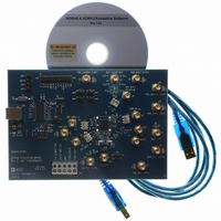
Manufacturer Part Number
AD9549/PCBZ
Description
BOARD EVALUATION FOR AD9549
Manufacturer
Analog Devices Inc
Datasheet
1.AD9549ABCPZ.pdf
(76 pages)
Specifications of AD9549/PCBZ
Main Purpose
Timing, Clock Generator
Embedded
No
Utilized Ic / Part
AD9549
Primary Attributes
2 Inputs, 2 Outputs, VCO
Secondary Attributes
CMOS, HSTL Output Logic, Graphical User Interface
Lead Free Status / RoHS Status
Lead free / RoHS Compliant


AD9549
Register 0x0104—S-Divider (DPLL Feedback Divider)
Table 27.
Bits
[7:0]
Register 0x0105—S-Divider (DPLL Feedback Divider) (Continued)
Table 28.
Bits
[15:8]
Register 0x0106—S-Divider (DPLL Feedback Divider) (Continued)
Table 29.
Bits
7
[6:1]
0
Register 0x0107—P-Divider
Table 30.
Bits
[4:0]
Register 0x0108—Loop Coefficients
See the Digital Loop Filter Coefficients section. Note that the AD9549 evaluation software derives these values.
Table 31.
Bits
[7:0]
Register 0x0109—Loop Coefficients (Continued)
Table 32.
Bits
[11:8]
Bit Name
S-divider
Bit Name
S-divider
Bit Name
Falling edge triggered
Reserved
S-divider/2
Bit Name
P-divider
Bit Name
Alpha-0
Bit Name
Alpha-0
Description
Feedback divider. Divide ratio = 1 − 65,536. If the desired feedback ratio is greater than 65,536, or if
the feedback signal on FDBK_IN is greater than 400 MHz, then Bit 0 of Register 0x0106 must be set.
Note that the actual S-divider is the value in this register plus 1, so to have an R-divider of 1,
Register 0x0104 and Register 0x0105 must both be 0x00. Register 0x0104 is the least significant byte.
Description
Setting this bit inverts the reference clock before S-divider.
Reserved.
Setting this bit enables an additional /2 prescaler. See the Feedback Divider (Divide-by-S) section.
If the desired feedback ratio is greater than 65,536, or if the feedback signal on FDBK_IN is greater
than 400 MHz, then this bit must be set. An example of this case is when the PLL is locking to an
image of the DAC output that is above the Nyquist frequency.
Description
Divide ratio. Controls the ratio of DAC sample rate to loop filter sample rate. See the Digital Loop
Filter section. Loop filter sample rate = DAC sample rate/2^(divide ratio[4:0]). For the default case
of 1 GHz DAC sample rate, and P-divider[4:0] of 5, the loop filter sample rate is 31.25 MHz. Note that
the DAC sample rate is the same as system clock.
Description
Linear coefficient for alpha coefficient.
Description
Linear coefficient for alpha coefficient.
Rev. D | Page 56 of 76
Related parts for AD9549/PCBZ
Image
Part Number
Description
Manufacturer
Datasheet
Request
R


Part Number:
Description:
±1.7g Dual-Axis IMEMS Accelerometer Evaluation Board
Manufacturer:
Analog Devices Inc
Datasheet:

Part Number:
Description:
Inertial Sensor Evaluation System
Manufacturer:
Analog Devices Inc
Datasheet:
Part Number:
Description:
Manufacturer:
Analog Devices Inc
Datasheet:
Part Number:
Description:
Manufacturer:
Analog Devices Inc
Datasheet:
Part Number:
Description:
Manufacturer:
Analog Devices Inc
Datasheet:
Part Number:
Description:
Manufacturer:
Analog Devices Inc
Datasheet:
Part Number:
Description:
Manufacturer:
Analog Devices Inc
Datasheet:
Part Number:
Description:
Manufacturer:
Analog Devices Inc
Datasheet:
Part Number:
Description:
Manufacturer:
Analog Devices Inc
Datasheet:
Part Number:
Description:
Manufacturer:
Analog Devices Inc
Datasheet:
Part Number:
Description:
Manufacturer:
Analog Devices Inc
Datasheet:
Part Number:
Description:
Manufacturer:
Analog Devices Inc
Datasheet: