PESD5V0S4UF,115 NXP Semiconductors, PESD5V0S4UF,115 Datasheet
PESD5V0S4UF,115
Specifications of PESD5V0S4UF,115
PESD5V0S4UF T/R
PESD5V0S4UF T/R


Related parts for PESD5V0S4UF,115


PESD5V0S4UF,115 Summary of contents
Page 1
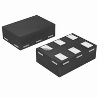
PESD3V3S4UF; PESD5V0S4UF Unidirectional quadruple ESD protection diode arrays Rev. 01 — 17 January 2008 1. Product profile 1.1 General description Unidirectional quadruple ElectroStatic Discharge (ESD) protection diode arrays in a small SOT886 Surface-Mounted Device (SMD) plastic package designed to protect ...
Page 2
... NXP Semiconductors 2. Pinning information Table 2. Pin Ordering information Table 3. Type number PESD3V3S4UF PESD5V0S4UF 4. Marking Table 4. Type number PESD3V3S4UF PESD5V0S4UF [ made in Hong Kong * = p: made in Hong Kong * = t: made in Malaysia * = W: made in China 5. Limiting values Table 5. In accordance with the Absolute Maximum Rating System (IEC 60134). ...
Page 3
... NXP Semiconductors Table 5. In accordance with the Absolute Maximum Rating System (IEC 60134). Symbol Per device amb T stg [1] Non-repetitive current pulse 8/20 s exponential decay waveform according to IEC 61000-4-5. [2] Measured from pin pin Table unless otherwise specified. amb Symbol Per diode ...
Page 4
... NXP Semiconductors 6. Characteristics Table unless otherwise specified. amb Symbol Parameter Per diode V RWM dif [1] Non-repetitive current pulse 8/20 s exponential decay waveform according to IEC 61000-4-5. [2] Measured from pin pin PESD3V3S4UF_PESD5V0S4UF_1 Product data sheet PESD3V3S4UF; PESD5V0S4UF Unidirectional quadruple ESD protection diode arrays ...
Page 5
... NXP Semiconductors ( amb Fig 3. Peak pulse power as a function of exponential pulse duration; typical values 120 C d (pF) 80 (1) ( MHz amb (1) PESD3V3S4UF (2) PESD5V0S4UF Fig 5. Diode capacitance as a function of reverse voltage; typical values PESD3V3S4UF_PESD5V0S4UF_1 Product data sheet PESD3V3S4UF; PESD5V0S4UF Unidirectional quadruple ESD protection diode arrays 006aab146 1 ...
Page 6
... NXP Semiconductors Fig 7. V-I characteristics for a unidirectional ESD protection diode PESD3V3S4UF_PESD5V0S4UF_1 Product data sheet PESD3V3S4UF; PESD5V0S4UF Unidirectional quadruple ESD protection diode arrays RWM P Rev. 01 — 17 January 2008 V 006aaa407 © NXP B.V. 2008. All rights reserved ...
Page 7
... NXP Semiconductors ESD TESTER IEC 61000-4-2 network C = 150 pF 330 Z Z GND unclamped +1 kV ESD voltage waveform (IEC 61000-4-2 network) GND unclamped 1 kV ESD voltage waveform (IEC 61000-4-2 network) Fig 8. ESD clamping test setup and waveforms PESD3V3S4UF_PESD5V0S4UF_1 Product data sheet PESD3V3S4UF; PESD5V0S4UF ...
Page 8
... NXP Semiconductors 7. Application information The PESDxS4UF is designed for the protection four unidirectional data or signal lines from the damage caused by ESD and surge pulses. The PESDxS4UF may be used on lines where the signal polarities are either positive or negative with respect to ground. The PESDxS4UF provides a surge capability of 110 W per line for an 8/20 s waveform each ...
Page 9
... NXP Semiconductors 8. Package outline Fig 10. Package outline PESDxS4UF (SOT886) 9. Packing information Table 9. The indicated -xxx are the last three digits of the 12NC ordering code. Type number PESD3V3S4UF SOT886 PESD5V0S4UF SOT886 [1] For further information and the availability of packing methods, see [2] T1: normal taping ...
Page 10
... NXP Semiconductors 10. Soldering Fig 11. Reflow soldering footprint PESDxS4UF (SOT886) PESD3V3S4UF_PESD5V0S4UF_1 Product data sheet PESD3V3S4UF; PESD5V0S4UF Unidirectional quadruple ESD protection diode arrays 1.250 0.675 0.370 (6 ) 0.270 (6 ) 0.325 0.425 ( Reflow soldering is the only recommended soldering method. Rev. 01 — 17 January 2008 0.500 1.700 solder lands 0 ...
Page 11
... NXP Semiconductors 11. Revision history Table 10. Revision history Document ID PESD3V3S4UF_PESD5V0S4UF_1 20080117 PESD3V3S4UF_PESD5V0S4UF_1 Product data sheet PESD3V3S4UF; PESD5V0S4UF Unidirectional quadruple ESD protection diode arrays Release date Data sheet status Product data sheet Rev. 01 — 17 January 2008 Change notice Supersedes - - © NXP B.V. 2008. All rights reserved. ...
Page 12
... Right to make changes — NXP Semiconductors reserves the right to make changes to information published in this document, including without limitation specifications and product descriptions, at any time and without notice ...
Page 13
... NXP Semiconductors 14. Contents 1 Product profi 1.1 General description 1.2 Features . . . . . . . . . . . . . . . . . . . . . . . . . . . . . . 1 1.3 Applications . . . . . . . . . . . . . . . . . . . . . . . . . . . 1 1.4 Quick reference data Pinning information . . . . . . . . . . . . . . . . . . . . . . 2 3 Ordering information . . . . . . . . . . . . . . . . . . . . . 2 4 Marking . . . . . . . . . . . . . . . . . . . . . . . . . . . . . . . . 2 5 Limiting values Characteristics . . . . . . . . . . . . . . . . . . . . . . . . . . 4 7 Application information Package outline . . . . . . . . . . . . . . . . . . . . . . . . . 9 9 Packing information Soldering . . . . . . . . . . . . . . . . . . . . . . . . . . . . . 10 11 Revision history . . . . . . . . . . . . . . . . . . . . . . . . 11 12 Legal information ...