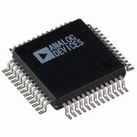
ADUC834BSZ Analog Devices Inc, ADUC834BSZ Datasheet - Page 27

ADUC834BSZ
Manufacturer Part Number
ADUC834BSZ
Description
IC ADC DUAL16/24BIT W/MCU 52MQFP
Manufacturer
Analog Devices Inc
Series
MicroConverter® ADuC8xxr
Specifications of ADUC834BSZ
Core Size
8-Bit
Program Memory Size
62KB (62K x 8)
Oscillator Type
Internal
Core Processor
8052
Speed
12.58MHz
Connectivity
EBI/EMI, I²C, SPI, UART/USART
Peripherals
POR, PSM, PWM, Temp Sensor, WDT
Number Of I /o
34
Program Memory Type
FLASH
Eeprom Size
4K x 8
Ram Size
2.25K x 8
Voltage - Supply (vcc/vdd)
2.7 V ~ 5.25 V
Data Converters
A/D 3x16b, 4x24b; D/A 1x12b
Operating Temperature
-40°C ~ 125°C
Package / Case
52-MQFP, 52-PQFP
Controller Family/series
(8052) ADUC
No. Of I/o's
26
Eeprom Memory Size
62KB
Ram Memory Size
2KB
Cpu Speed
12.58MHz
Package
52MQFP
Device Core
8052
Family Name
ADuC8xx
Maximum Speed
12.58 MHz
Operating Supply Voltage
3.3|5 V
Data Bus Width
8 Bit
Number Of Programmable I/os
26
Interface Type
I2C/SPI/UART
On-chip Adc
4-chx16-bit|4-chx24-bit
On-chip Dac
1-chx12-bit
Number Of Timers
3
Lead Free Status / RoHS Status
Lead free / RoHS Compliant
Available stocks
Company
Part Number
Manufacturer
Quantity
Price
Company:
Part Number:
ADUC834BSZ
Manufacturer:
TOSHIBA
Quantity:
1 200
Company:
Part Number:
ADUC834BSZ
Manufacturer:
Analog Devices Inc
Quantity:
10 000
Part Number:
ADUC834BSZ
Manufacturer:
ADI/亚德诺
Quantity:
20 000
In operation, the analog signal sample is fed to the difference
amplifier along with the output of the feedback DAC. The
difference between these two signals is integrated and fed to the
comparator. The output of the comparator provides the input to
the feedback DAC so the system functions as a negative feedback
loop that tries to minimize the difference signal. The digital
data that represents the analog input voltage is contained in the
duty cycle of the pulse train appearing at the output of the com-
parator. This duty cycle data can be recovered as a data-word
using a subsequent digital filter stage. The sampling frequency of
the modulator loop is many times higher than the bandwidth
of the input signal. The integrator in the modulator shapes the
quantization noise (which results from the analog-to-digital
conversion) so that the noise is pushed toward one-half of the
modulator frequency.
Digital Filter
The output of the - modulator feeds directly into the digital
filter. The digital filter then band-limits the response to a fre-
quency significantly lower than one-half of the modulator frequency.
In this manner, the 1-bit output of the comparator is translated
into a band-limited, low noise output from the ADuC834 ADCs.
The ADuC834 filter is a low-pass, Sinc
whose primary function is to remove the quantization noise
introduced at the modulator. The cutoff frequency and decimated
output data rate of the filter are programmable via the SF (Sinc
Filter) SFR as described in Table VIII.
Figure 11 shows the frequency response of the ADC channel at
the default SF word of 69 dec or 45H, yielding an overall output
update rate of just under 20 Hz.
It should be noted that this frequency response allows frequency
components higher than the ADC Nyquist frequency to pass
through the ADC, in some cases without significant attenuation.
These components may, therefore, be aliased and appear
in-band after the sampling process.
It should also be noted that rejection of mains-related frequency
components, i.e., 50 Hz and 60 Hz, is seen to be at a level of
>65 dB at 50 Hz and >100 dB at 60 Hz. This confirms the data
sheet specifications for 50 Hz/60 Hz Normal Mode Rejection
(NMR) at a 20 Hz update rate.
REV. A
–100
–110
–120
–10
–20
–30
–40
–50
–60
–70
–80
–90
0
Figure 11. Filter Response, SF = 69 dec
0
10
20
30
40
FREQUENCY – Hz
50
60
3
70
or (SIN x/x)3 filter
80
90
100 110
–27–
The response of the filter, however, will change with SF word as
can be seen in Figure 12, which shows >90 dB NMR at 50 Hz
and >70 dB NMR at 60 Hz when SF = 255 dec.
Figures 13 and 14 show the NMR for 50 Hz and 60 Hz across
the full range of SF word, i.e., SF = 13 dec to SF = 255 dec.
Figure 13. 50 Hz Normal Mode Rejection vs. SF
Figure 14. 60 Hz Normal Mode Rejection vs. SF
–100
–110
–120
–100
–110
–120
–100
–110
–120
–10
–20
–30
–40
–50
–60
–70
–80
–90
–10
–20
–30
–40
–50
–60
–70
–80
–90
–10
–20
–30
–40
–50
–60
–70
–80
–90
0
0
0
Figure 12. Filter Response, SF = 255 dec
10
10
0
30
30
10
50
50
20
70
70
30
90
90
FREQUENCY – Hz
110
110
40
SF – Decimal
SF – Decimal
130
130
50
150 170 190 210
150 170 190 210
60
70
ADuC834
80
230 250
230 250
90
110


