MPC5125YVN400 Freescale Semiconductor, MPC5125YVN400 Datasheet - Page 867
MPC5125YVN400
Manufacturer Part Number
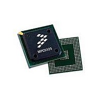
MPC5125YVN400
Description
IC MCU 32BIT E300 324TEPBGA
Manufacturer
Freescale Semiconductor
Series
MPC51xxr
Datasheets
1.MPC5125YVN400.pdf
(92 pages)
2.MPC5125YVN400.pdf
(8 pages)
3.MPC5125YVN400.pdf
(2 pages)
4.MPC5125YVN400.pdf
(1064 pages)
Specifications of MPC5125YVN400
Core Processor
e300
Core Size
32-Bit
Speed
400MHz
Connectivity
CAN, EBI/EMI, Ethernet, I²C, USB OTG
Peripherals
DMA, WDT
Number Of I /o
64
Program Memory Type
ROMless
Ram Size
32K x 8
Voltage - Supply (vcc/vdd)
1.33 V ~ 1.47 V
Oscillator Type
External
Operating Temperature
-40°C ~ 125°C
Package / Case
324-PBGA
Processor Series
MPC51xx
Core
e300
Data Bus Width
32 bit
Development Tools By Supplier
TWR-MPC5125-KIT, TWR-SER, TWR-ELEV, TOWER
Maximum Clock Frequency
400 MHz
Operating Supply Voltage
1.4 V
Maximum Operating Temperature
+ 125 C
Mounting Style
SMD/SMT
Data Ram Size
32 KB
I/o Voltage
3.3 V
Interface Type
CAN, I2C
Minimum Operating Temperature
- 40 C
Program Memory Size
32 bit
Cpu Speed
400MHz
Embedded Interface Type
CAN, I2C, SPI, UART, USB
Digital Ic Case Style
TEPBGA
No. Of Pins
324
Rohs Compliant
Yes
Cpu Family
MPC5xx
Device Core Size
32b
Frequency (max)
400MHz
Total Internal Ram Size
32KB
Instruction Set Architecture
RISC
Operating Temp Range
-40C to 85C
Operating Temperature Classification
Industrial
Mounting
Surface Mount
Pin Count
324
Lead Free Status / RoHS Status
Lead free / RoHS Compliant
Eeprom Size
-
Program Memory Size
-
Data Converters
-
Lead Free Status / Rohs Status
Lead free / RoHS Compliant
Available stocks
Company
Part Number
Manufacturer
Quantity
Price
Company:

Part Number:
MPC5125YVN400
Manufacturer:
Freescale Semiconductor
Quantity:
135
Company:
Part Number:
MPC5125YVN400
Manufacturer:
LTC
Quantity:
29
Company:
Part Number:
MPC5125YVN400
Manufacturer:
Freescale Semiconductor
Quantity:
10 000


Freescale Semiconductor
WKDS
WKCN
Field
HSP
PTC
PIC
PO
PP
LS
Wake On Disconnect Enable. Writing this bit to 1 enables the port to be sensitive to device disconnects as
wake-up events.
This field is 0 if Port Power (PP) is 0 or in device mode.
This bit is (OTG/host mode only) for use by an external power control circuit.
Wake On Connect Enable. Writing this bit to 1 enables the port to be sensitive to device connects as wake-up
events.
This field is 0 if Port Power (PP) is 0 or in device mode.
Port Test Control. Any value other than zero indicates the port is operating in test mode.
0000 Not Enabled.
0001 J_STATE.
0010 K_STATE.
0011 SE0_NAK.
0100 Packet.
0101 FORCE_ENABLE.
0110-1111 Reserved.
Refer to Chapter 7 of the USB Specification Revision 2.0 [3] for details on each test mode.
Port Indicator Control. These bits control the link indicator signals. These signals are valid for host mode only.
00 Off.
01 Amber.
10 Green.
11 Undefined.
Refer to the USB Specification Revision 2.0 [3] for a description on how these bits are to be used.
This field is output from the module on the USB port control signals for use by an external LED driving circuit.
Port Owner. This bit unconditionally goes to a 0 when the configured bit in the USB_CONFIGFLAG register
makes a 0 to 1 transition. This bit unconditionally goes to 1 when the configured bit is zero. System software
uses this field to release ownership of the port to a selected module (in the event that the attached device is
not a high-speed device). Software writes a 1 to this bit when the attached device is not a high-speed device.
A one in this bit means an internal companion controller owns and controls the port.
Port owner hand-off is not implemented in this design, therefore this bit is always 0.
Port Power. This bit represents the current setting of the switch (0 = off, 1 = on). When power is not available
on a port (i.e., PP = 0), the port is non-functional and does not report attaches, detaches, etc.
When an over-current condition is detected on a powered port, the PP bit in each affected port is transitioned
by the host controller driver from a 1 to a 0 (removing power from the port).
This feature is implemented in the host/OTG controller (PPC = 1).
For the OTG module in a device-only implementation, port power control is not necessary. Therefore, PPC
and PP equal 0.
Line Status. These bits reflect the current logical levels of the USB D+ (bit 11) and D– (bit 10) signal lines. The
use of line status by the host controller driver is not necessary (unlike EHCI) because hardware manages the
connection of FS and LS.
00 SE0.
01 J-state.
10 K-state.
11 Undefined.
High Speed Port.
This bit is redundant with the USB_PORTSCn[PSPD] bits.
1 Host/Device connected is operating in High Speed mode.
0 Host/Device connected is not operating in High Speed mode.
This field is 0 if Port Power (PP) is 0.
Table 32-32. USB_PORTSCn field descriptions (continued)
MPC5125 Microcontroller Reference Manual, Rev. 2
Description
Universal Serial Bus Interface with On-The-Go
32-39
Related parts for MPC5125YVN400
Image
Part Number
Description
Manufacturer
Datasheet
Request
R

Part Number:
Description:
Mpc5125 Microcontroller Data Sheet
Manufacturer:
Freescale Semiconductor, Inc
Datasheet:

Part Number:
Description:
MPC5125 Microcontroller Data Sheet
Manufacturer:
FREESCALE [Freescale Semiconductor, Inc]
Datasheet:
Part Number:
Description:
Manufacturer:
Freescale Semiconductor, Inc
Datasheet:
Part Number:
Description:
Manufacturer:
Freescale Semiconductor, Inc
Datasheet:
Part Number:
Description:
Manufacturer:
Freescale Semiconductor, Inc
Datasheet:
Part Number:
Description:
Manufacturer:
Freescale Semiconductor, Inc
Datasheet:
Part Number:
Description:
Manufacturer:
Freescale Semiconductor, Inc
Datasheet:
Part Number:
Description:
Manufacturer:
Freescale Semiconductor, Inc
Datasheet:
Part Number:
Description:
Manufacturer:
Freescale Semiconductor, Inc
Datasheet:
Part Number:
Description:
Manufacturer:
Freescale Semiconductor, Inc
Datasheet:
Part Number:
Description:
Manufacturer:
Freescale Semiconductor, Inc
Datasheet:
Part Number:
Description:
Manufacturer:
Freescale Semiconductor, Inc
Datasheet:
Part Number:
Description:
Manufacturer:
Freescale Semiconductor, Inc
Datasheet:
Part Number:
Description:
Manufacturer:
Freescale Semiconductor, Inc
Datasheet:
Part Number:
Description:
Manufacturer:
Freescale Semiconductor, Inc
Datasheet: