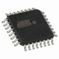
ATMEGA64M1-AU Atmel, ATMEGA64M1-AU Datasheet - Page 199

ATMEGA64M1-AU
Manufacturer Part Number
ATMEGA64M1-AU
Description
IC MCU AVR 64K FLASH 32TQFP
Manufacturer
Atmel
Series
AVR® ATmegar
Specifications of ATMEGA64M1-AU
Core Processor
AVR
Core Size
8-Bit
Speed
16MHz
Connectivity
CAN, LIN, SPI, UART/USART
Peripherals
Brown-out Detect/Reset, POR, PWM, Temp Sensor, WDT
Program Memory Size
64KB (32K x 16)
Program Memory Type
FLASH
Eeprom Size
2K x 8
Ram Size
4K x 8
Voltage - Supply (vcc/vdd)
2.7 V ~ 5.5 V
Data Converters
A/D 11x10b; D/A 1x10b
Oscillator Type
Internal
Operating Temperature
-40°C ~ 85°C
Package / Case
32-TQFP, 32-VQFP
Lead Free Status / RoHS Status
Lead free / RoHS Compliant
Number Of I /o
-
Lead Free Status / Rohs Status
Details
Available stocks
Company
Part Number
Manufacturer
Quantity
Price
- Current page: 199 of 341
- Download datasheet (6Mb)
20.3
20.3.1
20.3.2
Figure 20-3. Structure of a LIN frame
8209D–AVR–11/10
LIN Protocol
Master and Slave
Frames
BREAK
Break Delimiter
Field
A LIN cluster consists of one master task and several slave tasks. A master node contains the
master task as well as a slave task. All other nodes contain a slave task only.
Figure 20-1. LIN cluster with one master node and “n” slave nodes
The master task decides when and which frame shall be transferred on the bus. The slave tasks
provide the data transported by each frame. Both the master task and the slave task are parts of
the Frame handler.
A frame consists of a header (provided by the master task) and a response (provided by a slave
task).
The header consists of a BREAK and SYNC pattern followed by a PROTECTED IDENTIFIER.
The identifier uniquely defines the purpose of the frame. The slave task appointed for providing
the response associated with the identifier transmits it. The response consists of a DATA field
and a CHECKSUM field.
Figure 20-2. Master and slave tasks behavior in LIN frame
The slave tasks waiting for the data associated with the identifier receives the response and
uses the data transported after verifying the checksum.
HEADER
Slave Task 1
Slave Task 2
Master Task
SYNC
Field
master node
master task
slave task
PROTECTED
IDENTIFIER
HEADER
Response Space
Field
FRAME SLOT
RESPONSE
DATA-0
slave node
slave task
LIN bus
Field
1
ATmega16M1/32M1/64M1
RESPONSE
Each byte field is transmitted as a serial byte, LSB first.
DATA-n
HEADER
Inter-Byte Space
Field
slave node
slave task
CHECKSUM
n
RESPONSE
Field
Inter-Frame Space
199
Related parts for ATMEGA64M1-AU
Image
Part Number
Description
Manufacturer
Datasheet
Request
R

Part Number:
Description:
Manufacturer:
Atmel Corporation
Datasheet:

Part Number:
Description:
Manufacturer:
ATMEL Corporation
Datasheet:

Part Number:
Description:
Manufacturer:
ATMEL Corporation
Datasheet:

Part Number:
Description:
IC AVR MCU 64K 16MHZ 5V 64TQFP
Manufacturer:
Atmel
Datasheet:

Part Number:
Description:
IC AVR MCU 64K 16MHZ 5V 64-QFN
Manufacturer:
Atmel
Datasheet:

Part Number:
Description:
IC AVR MCU 64K 16MHZ COM 64-TQFP
Manufacturer:
Atmel
Datasheet:

Part Number:
Description:
IC AVR MCU 64K 16MHZ IND 64-TQFP
Manufacturer:
Atmel
Datasheet:

Part Number:
Description:
IC AVR MCU 64K 16MHZ COM 64-QFN
Manufacturer:
Atmel
Datasheet:

Part Number:
Description:
MCU AVR 64KB FLASH 16MHZ 64TQFP
Manufacturer:
Atmel
Datasheet:

Part Number:
Description:
MCU AVR 64KB FLASH 16MHZ 64QFN
Manufacturer:
Atmel
Datasheet:

Part Number:
Description:
IC AVR MCU 64K 16MHZ IND 64-QFN
Manufacturer:
Atmel
Datasheet:

Part Number:
Description:
IC MCU AVR 64K 5V 16MHZ 64-TQFP
Manufacturer:
Atmel
Datasheet:

Part Number:
Description:
IC MCU AVR 64K 5V 16MHZ 64-QFN
Manufacturer:
Atmel
Datasheet:

Part Number:
Description:
MCU 8-Bit ATmega AVR RISC 64KB Flash 5V 64-Pin TQFP T/R
Manufacturer:
Atmel
Datasheet:


