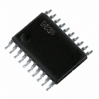
P87LPC764BDH,512 NXP Semiconductors, P87LPC764BDH,512 Datasheet - Page 31

P87LPC764BDH,512
Manufacturer Part Number
P87LPC764BDH,512
Description
IC 80C51 MCU 4K OTP 20-TSSOP
Manufacturer
NXP Semiconductors
Series
LPC700r
Datasheet
1.P87LPC764BD512.pdf
(60 pages)
Specifications of P87LPC764BDH,512
Program Memory Type
OTP
Program Memory Size
4KB (4K x 8)
Package / Case
20-TSSOP
Core Processor
8051
Core Size
8-Bit
Speed
20MHz
Connectivity
I²C, UART/USART
Peripherals
Brown-out Detect/Reset, LED, POR, WDT
Number Of I /o
18
Ram Size
128 x 8
Voltage - Supply (vcc/vdd)
2.7 V ~ 6 V
Oscillator Type
Internal
Operating Temperature
0°C ~ 70°C
Processor Series
P87LPC7x
Core
80C51
Data Bus Width
8 bit
Data Ram Size
128 B
Interface Type
I2C/UART
Maximum Clock Frequency
20 MHz
Number Of Programmable I/os
18
Number Of Timers
2
Operating Supply Voltage
2.7 V to 6 V
Maximum Operating Temperature
+ 70 C
Mounting Style
SMD/SMT
3rd Party Development Tools
PK51, CA51, A51, ULINK2
Minimum Operating Temperature
0 C
Package
20TSSOP
Device Core
80C51
Family Name
87LP
Maximum Speed
20 MHz
Lead Free Status / RoHS Status
Lead free / RoHS Compliant
For Use With
OM10063 - PROGRAMMER LPC700 P76XLCPOM10050 - EMULATOR LPC700 PDS76X
Eeprom Size
-
Data Converters
-
Lead Free Status / Rohs Status
Lead free / RoHS Compliant
Other names
568-1259-5
935267867512
P87LPC764BDH
935267867512
P87LPC764BDH
Available stocks
Company
Part Number
Manufacturer
Quantity
Price
Company:
Part Number:
P87LPC764BDH,512
Manufacturer:
NXP
Quantity:
747
Philips Semiconductors
Mode 1
Mode 1 is the same as Mode 0, except that all 16 bits of the timer
register (THn and TLn) are used. See Figure 25
Mode 2
Mode 2 configures the Timer register as an 8-bit Counter (TL1) with
automatic reload, as shown in Figure 26. Overflow from TLn not only
sets TFn, but also reloads TLn with the contents of THn, which must
be preset by software. The reload leaves THn unchanged. Mode 2
operation is the same for Timer 0 and Timer 1.
Mode 3
When Timer 1 is in Mode 3 it is stopped. The effect is the same as
setting TR1 = 0.
2003 Sep 03
Low power, low price, low pin count (20 pin)
microcontroller with 4 kbyte OTP
OSC/6
OSC/6
OSC/12
OSC/12
INTn PIN
INTn PIN
Tn PIN
Tn PIN
GATE
GATE
TRn
TRn
OR
or
Figure 26. Timer/Counter 0 or 1 in Mode 2 (8-Bit Auto-Reload)
C/T = 1
C/T = 1
Figure 25. Timer/Counter 0 or 1 in Mode 1 (16-Bit Counter)
C/T = 0
C/T = 0
CONTROL
CONTROL
30
Timer 0 in Mode 3 establishes TL0 and TH0 as two separate 8-bit
counters. The logic for Mode 3 on Timer 0 is shown in Figure 27.
TL0 uses the Timer 0 control bits: C/T, GATE, TR0 and pin INT0,
and TF0. TH0 is locked into a timer function (counting machine
cycles) and takes over the use of TR1 and TF1 from Timer 1. Thus,
TH0 now controls the “Timer 1” interrupt.
Mode 3 is provided for applications that require an extra 8-bit timer.
With Timer 0 in Mode 3, an P87LPC764 can look like it has three
Timer/Counters. When Timer 0 is in Mode 3, Timer 1 can be turned
on and off by switching it into and out of its own Mode 3. It can still
be used by the serial port as a baud rate generator, or in any
application not requiring an interrupt.
(8 BITS)
(8 BITS)
(8 BITS)
THn
TLn
TLn
RELOAD
(8 BITS)
THn
OVERFLOW
TOGGLE
TOGGLE
OVERFLOW
TnOE
TnOE
TFn
TFn
P87LPC764
INTERRUPT
Tn PIN
INTERRUPT
Tn PIN
SU01174
SU01392
Product data


