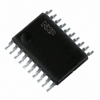
P87LPC764BDH,512 NXP Semiconductors, P87LPC764BDH,512 Datasheet - Page 43

P87LPC764BDH,512
Manufacturer Part Number
P87LPC764BDH,512
Description
IC 80C51 MCU 4K OTP 20-TSSOP
Manufacturer
NXP Semiconductors
Series
LPC700r
Datasheet
1.P87LPC764BD512.pdf
(60 pages)
Specifications of P87LPC764BDH,512
Program Memory Type
OTP
Program Memory Size
4KB (4K x 8)
Package / Case
20-TSSOP
Core Processor
8051
Core Size
8-Bit
Speed
20MHz
Connectivity
I²C, UART/USART
Peripherals
Brown-out Detect/Reset, LED, POR, WDT
Number Of I /o
18
Ram Size
128 x 8
Voltage - Supply (vcc/vdd)
2.7 V ~ 6 V
Oscillator Type
Internal
Operating Temperature
0°C ~ 70°C
Processor Series
P87LPC7x
Core
80C51
Data Bus Width
8 bit
Data Ram Size
128 B
Interface Type
I2C/UART
Maximum Clock Frequency
20 MHz
Number Of Programmable I/os
18
Number Of Timers
2
Operating Supply Voltage
2.7 V to 6 V
Maximum Operating Temperature
+ 70 C
Mounting Style
SMD/SMT
3rd Party Development Tools
PK51, CA51, A51, ULINK2
Minimum Operating Temperature
0 C
Package
20TSSOP
Device Core
80C51
Family Name
87LP
Maximum Speed
20 MHz
Lead Free Status / RoHS Status
Lead free / RoHS Compliant
For Use With
OM10063 - PROGRAMMER LPC700 P76XLCPOM10050 - EMULATOR LPC700 PDS76X
Eeprom Size
-
Data Converters
-
Lead Free Status / Rohs Status
Lead free / RoHS Compliant
Other names
568-1259-5
935267867512
P87LPC764BDH
935267867512
P87LPC764BDH
Available stocks
Company
Part Number
Manufacturer
Quantity
Price
Company:
Part Number:
P87LPC764BDH,512
Manufacturer:
NXP
Quantity:
747
Philips Semiconductors
2003 Sep 03
Low power, low price, low pin count (20 pin)
microcontroller with 4 kbyte OTP
WDCON
BIT
WDCON.7, 6
WDCON.5
WDCON.4
WDCON.3
WDCON.2–0 WDS2–0
RC OSCILLATOR
Address: A7h
Not Bit Addressable
500 kHz
CLOCK OUT
WDCLK * WDTE
STATE CLOCK
ENABLE
SYMBOL
WDS2–0
WDRUN
WDOVF
WDCLK
0 0 0
0 0 1
0 1 0
0 1 1
1 0 0
1 0 1
1 1 0
1 1 1
—
—
7
FEED DETECT
WATCHDOG
BOF (PCON.5)
POF (PCON.4)
FUNCTION
Reserved for future use. Should not be set to 1 by user programs.
Watchdog timer overflow flag. Set when a watchdog reset or timer overflow occurs. Cleared when
the watchdog is fed.
Watchdog run control. The watchdog timer is started when WDRUN = 1 and stopped when
WDRUN = 0. This bit is forced to 1 (watchdog running) if the WDTE configuration bit = 1.
Watchdog clock select. The watchdog timer is clocked by CPU clock/6 when WDCLK = 1 and by
the watchdog RC oscillator when WDCLK = 0. This bit is forced to 0 (using the watchdog RC
oscillator) if the WDTE configuration bit = 1.
Watchdog rate select.
Timeout Clocks
Reset Value:
—
6
1,048,576
131,072
262,144
524,288
WDTE + WDRUN
Figure 34. Watchdog Timer Control Register (WDCON)
16,384
32,768
65,536
8,192
Figure 33. Block Diagram of the Watchdog Timer
WDOVF
5
10h for other rest sources if the watchdog is enabled via the WDTE configuration bit.
00h for other reset sources if the watchdog is disabled via the WDTE configuration bit.
30h for a watchdog reset.
WDRUN
Minimum Time
4
165 ms
330 ms
660 ms
1.3 sec
(WDCON.2–0)
10 ms
20 ms
41 ms
82 ms
WDS2–0
WDCLK
42
CLEAR
3
20-BIT COUNTER
WDS2
8 TO 1 MUX
2
8 MSBs
Nominal Time
1.60 sec
3.20 sec
100 ms
200 ms
400 ms
800 ms
25 ms
50 ms
WDS1
1
WDS0
0
S
R
WDTE (UCFG1.7)
Maximum Time
Q
1280 ms
2.60 sec
5.30 sec
160 ms
320 ms
640 ms
40 ms
80 ms
P87LPC764
(WDCON.5)
WDOVF
WATCHDOG
WATCHDOG
INTERRUPT
RESET
SU01754
SU01476
Product data


