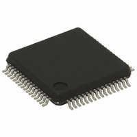
ST72F561AR6T3 STMicroelectronics, ST72F561AR6T3 Datasheet - Page 66

ST72F561AR6T3
Manufacturer Part Number
ST72F561AR6T3
Description
IC MCU 8BIT 32K FLASH 64-LQFP
Manufacturer
STMicroelectronics
Series
ST7r
Datasheet
1.ST72F561K6T6.pdf
(265 pages)
Specifications of ST72F561AR6T3
Core Processor
ST7
Core Size
8-Bit
Speed
8MHz
Connectivity
CAN, LINSCI, SPI
Peripherals
LVD, POR, PWM, WDT
Number Of I /o
48
Program Memory Size
32KB (32K x 8)
Program Memory Type
FLASH
Ram Size
1K x 8
Voltage - Supply (vcc/vdd)
3.8 V ~ 5.5 V
Data Converters
A/D 16x10b
Oscillator Type
External
Operating Temperature
-40°C ~ 125°C
Package / Case
64-LQFP
For Use With
497-8374 - BOARD DEVELOPMENT FOR ST72F561
Lead Free Status / RoHS Status
Lead free / RoHS Compliant
Eeprom Size
-
Available stocks
Company
Part Number
Manufacturer
Quantity
Price
Company:
Part Number:
ST72F561AR6T3
Manufacturer:
STMicroelectronics
Quantity:
10 000
- Current page: 66 of 265
- Download datasheet (10Mb)
ST72561
PWM AUTO-RELOAD TIMER (Cont’d)
Input Capture Function
Input Capture mode allows the measurement of
external signal pulse widths through ARTICRx
registers.
Each input capture can generate an interrupt inde-
pendently on a selected input signal transition.
This event is flagged by a set of the corresponding
CFx bits of the Input Capture Control/Status regis-
ter (ARTICCSR).
These input capture interrupts are enabled
through the CIEx bits of the ARTICCSR register.
The active transition (falling or rising edge) is soft-
ware programmable through the CSx bits of the
ARTICCSR register.
The read only input capture registers (ARTICRx)
are used to latch the auto-reload counter value
when a transition is detected on the ARTICx pin
(CFx bit set in ARTICCSR register). After fetching
the interrupt vector, the CFx flags can be read to
identify the interrupt source.
Note: After a capture detection, data transfer in
the ARTICRx register is inhibited until the next
read (clearing the CFx bit).
The timer interrupt remains pending while the CFx
flag is set when the interrupt is enabled (CIEx bit
Figure 45. Input Capture Timing Diagram, f
66/265
ICAP SAMPLED
ARTICx PIN
COUNTER
CFx FLAG
f
COUNTER
f
CPU
01h
02h
xxh
ICAP SAMPLED
03h
COUNTER
04h
set). This means, the ARTICRx register has to be
read at each capture event to clear the CFx flag.
The timing resolution is given by auto-reload coun-
ter cycle time (1/f
Note: During HALT mode, input capture is inhibit-
ed (the ARTICRx is never reloaded) and only the
external interrupt capability can be used.
Note: The ARTICx signal is synchronized on CPU
clock. It takes two rising edges until ARTICRx is
latched with the counter value. Depending on the
prescaler value and the time when the ICAP event
occurs, the value loaded in the ARTICRx register
may be different.
If the counter is clocked with the CPU clock, the
value latched in ARTICRx is always the next coun-
ter value after the event on ARTICx occurred
ure
If the counter clock is prescaled, it depends on the
position of the ARTICx event within the counter cy-
cle
= f
(Figure
CPU
45).
05h
46).
COUNTER
06h
).
05h
INTERRUPT
07h
t
(Fig-
Related parts for ST72F561AR6T3
Image
Part Number
Description
Manufacturer
Datasheet
Request
R

Part Number:
Description:
STMicroelectronics [RIPPLE-CARRY BINARY COUNTER/DIVIDERS]
Manufacturer:
STMicroelectronics
Datasheet:

Part Number:
Description:
STMicroelectronics [LIQUID-CRYSTAL DISPLAY DRIVERS]
Manufacturer:
STMicroelectronics
Datasheet:

Part Number:
Description:
BOARD EVAL FOR MEMS SENSORS
Manufacturer:
STMicroelectronics
Datasheet:

Part Number:
Description:
NPN TRANSISTOR POWER MODULE
Manufacturer:
STMicroelectronics
Datasheet:

Part Number:
Description:
TURBOSWITCH ULTRA-FAST HIGH VOLTAGE DIODE
Manufacturer:
STMicroelectronics
Datasheet:

Part Number:
Description:
Manufacturer:
STMicroelectronics
Datasheet:

Part Number:
Description:
DIODE / SCR MODULE
Manufacturer:
STMicroelectronics
Datasheet:

Part Number:
Description:
DIODE / SCR MODULE
Manufacturer:
STMicroelectronics
Datasheet:

Part Number:
Description:
Search -----> STE16N100
Manufacturer:
STMicroelectronics
Datasheet:

Part Number:
Description:
Search ---> STE53NA50
Manufacturer:
STMicroelectronics
Datasheet:

Part Number:
Description:
NPN Transistor Power Module
Manufacturer:
STMicroelectronics
Datasheet:

Part Number:
Description:
DIODE / SCR MODULE
Manufacturer:
STMicroelectronics
Datasheet:


