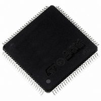
ST10R272LT1 STMicroelectronics, ST10R272LT1 Datasheet - Page 31

ST10R272LT1
Manufacturer Part Number
ST10R272LT1
Description
MCU 16BIT ROMLESS LV 100-TQFP
Manufacturer
STMicroelectronics
Series
ST10r
Datasheet
1.ST10R272LT1TR.pdf
(77 pages)
Specifications of ST10R272LT1
Core Processor
ST10
Core Size
16-Bit
Speed
50MHz
Connectivity
EBI/EMI, SSP, UART/USART
Peripherals
POR, PWM, WDT
Number Of I /o
77
Program Memory Type
ROMless
Ram Size
1K x 8
Voltage - Supply (vcc/vdd)
3 V ~ 3.6 V
Oscillator Type
Internal
Operating Temperature
0°C ~ 70°C
Package / Case
100-TQFP, 100-VQFP
Controller Family/series
ST10
No. Of I/o's
77
Ram Memory Size
1KB
Cpu Speed
50MHz
No. Of Timers
5
Embedded Interface Type
SPI, USART
No. Of Pwm Channels
1
Rohs Compliant
Yes
Processor Series
ST10R2x
Core
ST10
Data Bus Width
16 bit
Data Ram Size
1 KB
Interface Type
SSP, USART
Maximum Clock Frequency
50 MHz
Number Of Programmable I/os
77
Number Of Timers
5
Maximum Operating Temperature
+ 70 C
Mounting Style
SMD/SMT
Minimum Operating Temperature
0 C
On-chip Adc
16 bit
Case
QFP
Lead Free Status / RoHS Status
Lead free / RoHS Compliant
Eeprom Size
-
Program Memory Size
-
Data Converters
-
Lead Free Status / Rohs Status
Details
Available stocks
Company
Part Number
Manufacturer
Quantity
Price
Company:
Part Number:
ST10R272LT1
Manufacturer:
PANASONIC
Quantity:
30 000
Part Number:
ST10R272LT1
Manufacturer:
ST
Quantity:
20 000
Company:
Part Number:
ST10R272LT1/TR
Manufacturer:
STMicroelectronics
Quantity:
10 000
various commonly used baud rates together with the required reload values and the deviation
errors compared to the intended baudrate.
SSP transmits 1...3 bytes or receives 1 byte after sending 1...3 bytes synchronously to a shift
clock which is generated by the SSP. The SSP can start shifting with the LSB or with the MSB
and is used to select shifting and latching clock edges, and clock polarity. Up to two chip select
lines may be activated in order to direct data transfers to one or both of two peripheral devices.
When the SSP is enabled, the four upper pins of Port4 can not be used as general purpose
IO. Note that the segment address selection done via the system start-up configuration during
reset has priority and overrides the SSP functions on these pins.
S0BRS = ‘0’, f
Baud Rate
(Baud)
1562500
56000
38400
19200
9600
4800
2400
1200
600
190
SSPCKS Value
000
001
010
Table 10 Commonly used baud rates, required reload values and deviation errors
Deviation Error
0.0%
+3.3%
+1.7%
+0.5%
+0.5%
+0.2%
0.0%
0.0%
0.0%
+0.4%
CPU
Table 11 Synchronous baud rate and SSPCKS reload values
= 50MHz
/ 0.0%
/ -0.4%
/ -0.8%
/ -0.8%
/ -0.1%
/ -0.1%
/ -0.1%
/ -0.1%
/ 0.0%
/+0.4%
SSP clock = CPU clock divided by 2
SSP clock = CPU clock divided by 4
SSP clock = CPU clock divided by 8
Reload Value
0000
001A
0027
0050
00A1
0144
028A
0515
0A2B
1FFF
H
H
H
H
H
H
H
H
H
H
/ 00A2
/ 0000
/ 0028
/ 0051
/ 0145
/ 0516
/ 001B
/ 028B
/ 1FFF
/ 0A2C
H
H
H
H
H
H
H
H
H
H
S0BRS = ‘1’, f
Baud Rate
(Baud)
1041666
56000
38400
19200
9600
4800
2400
1200
600
75
127
ST10R272L - SERIAL CHANNELS
Deviation Error
0.0%
+3.3%
+0.5%
+0.5%
+0.5%
0.0%
0.0%
0.0%
0.0%
0.0%
+0.1%
CPU
= 50MHz
Synchronous baud rate
25 MBit/s
12.5 MBit/s
6.25 MBit/s
/ 0.0%
/ -2.1%
/ -3.1%
/-1.4%
/ -0.5%
/ -0.2%
/ -0.1%
/ -0.1%
/ 0.0%
/ +0.1% 1FFF
/ -0.5%
Reload Value
0000
0011
001A
0035
006B
00D8
01B1
0363
06C7
363F
H
H
H
H
H
H
H
H
H
H
H
/ 0000
/ 0012
/ 0036
/ 0364
/ 3640
/ 001B
/ 006C
/ 00D9
/ 01B2
/ 06C8
/ 1FFF
H
H
H
H
H
H
H
H
H
H
H
31/77
1


