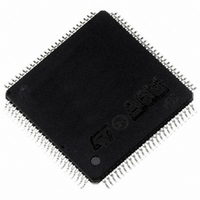
ST10R272LT1 STMicroelectronics, ST10R272LT1 Datasheet - Page 72

ST10R272LT1
Manufacturer Part Number
ST10R272LT1
Description
MCU 16BIT ROMLESS LV 100-TQFP
Manufacturer
STMicroelectronics
Series
ST10r
Datasheet
1.ST10R272LT1TR.pdf
(77 pages)
Specifications of ST10R272LT1
Core Processor
ST10
Core Size
16-Bit
Speed
50MHz
Connectivity
EBI/EMI, SSP, UART/USART
Peripherals
POR, PWM, WDT
Number Of I /o
77
Program Memory Type
ROMless
Ram Size
1K x 8
Voltage - Supply (vcc/vdd)
3 V ~ 3.6 V
Oscillator Type
Internal
Operating Temperature
0°C ~ 70°C
Package / Case
100-TQFP, 100-VQFP
Controller Family/series
ST10
No. Of I/o's
77
Ram Memory Size
1KB
Cpu Speed
50MHz
No. Of Timers
5
Embedded Interface Type
SPI, USART
No. Of Pwm Channels
1
Rohs Compliant
Yes
Processor Series
ST10R2x
Core
ST10
Data Bus Width
16 bit
Data Ram Size
1 KB
Interface Type
SSP, USART
Maximum Clock Frequency
50 MHz
Number Of Programmable I/os
77
Number Of Timers
5
Maximum Operating Temperature
+ 70 C
Mounting Style
SMD/SMT
Minimum Operating Temperature
0 C
On-chip Adc
16 bit
Case
QFP
Lead Free Status / RoHS Status
Lead free / RoHS Compliant
Eeprom Size
-
Program Memory Size
-
Data Converters
-
Lead Free Status / Rohs Status
Details
Available stocks
Company
Part Number
Manufacturer
Quantity
Price
Company:
Part Number:
ST10R272LT1
Manufacturer:
PANASONIC
Quantity:
30 000
Part Number:
ST10R272LT1
Manufacturer:
ST
Quantity:
20 000
Company:
Part Number:
ST10R272LT1/TR
Manufacturer:
STMicroelectronics
Quantity:
10 000
ST10R272L - ELECTRICAL CHARACTERISTICS
16.3.7
72/77
1
V
Parameter
Sync. RSTIN low time
RSTIN low to internal
reset sequence start
internal reset sequence,
(RSTIN internally pulled
low)
RSTIN rising edge to inter-
nal reset condition end
PORT0 system start-up
configuration setup to
RSTIN rising edge
PORT0 system start-up
configuration hold after
RSTIN rising edge
Bus signals drive from
internal reset end
RSTIN low to signals
release
ALE rising edge from inter-
nal reset condition end
Async. RSTIN low time
DD
1) On power-up reset, the RSTIN pin must be asserted until a stable clock signal is available
2) The value of bits 0 (EMU), 1 (ADAPT), 13 to 15 (Clock Configuration) are loaded during
= 3.3 V
(about 10...50 ms to allow the on-chip oscillator to stabilize) and until System Start-up Con-
figuration is correct on PORT0 (about 50 s for internal pullup devices to load 50 pF from
V
hardware reset as long as internal reset signal is active, and have an immediate effect on
the system.
IL
External Hardware Reset
min to V
0.3 V
IH
2))
min).
1)
1
Symbol
t
t
t
t
t
t
t
t
t
t
70
71
72
73
74
75
76
77
78
79
Table 21 External hardware reset
V
SS
SR
CC
CC
CC
SR
SR
CC
CC
CC
SR
= 0 V
Max. CPU Clock
= 50 MHz
min.
50
4
1024
4
100
1
0
–
8
1500
T
A
max.
–
16
1024
6
–
6
20
50
8
–
= -40 to +85 °C
min.
Variable CPU Clock
1/2TCL = 1 to 50 MHz
4 TCL + 10
4
1024
4
100
1
0
–
8
1500
C
L
= 50 pF
max.
–
16
1024
6
–
6
20
50
8
–
ns
TCL
TCL
TCL
ns
TCL
ns
ns
TCL
ns


