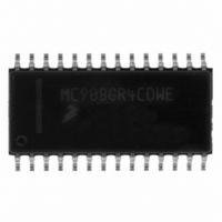
MC908GR4CDWE Freescale Semiconductor, MC908GR4CDWE Datasheet - Page 129

MC908GR4CDWE
Manufacturer Part Number
MC908GR4CDWE
Description
IC MCU 4K FLASH 8MHZ 28-SOIC
Manufacturer
Freescale Semiconductor
Series
HC08r
Specifications of MC908GR4CDWE
Core Processor
HC08
Core Size
8-Bit
Speed
8MHz
Connectivity
SCI, SPI
Peripherals
LVD, POR, PWM
Number Of I /o
17
Program Memory Size
4KB (4K x 8)
Program Memory Type
FLASH
Ram Size
384 x 8
Voltage - Supply (vcc/vdd)
2.7 V ~ 5.5 V
Data Converters
A/D 6x8b
Oscillator Type
Internal
Operating Temperature
-40°C ~ 85°C
Package / Case
28-SOIC (7.5mm Width)
Controller Family/series
HC08
No. Of I/o's
21
Ram Memory Size
384Byte
Cpu Speed
8MHz
No. Of Timers
1
Embedded Interface Type
I2C, SCI, SPI
Rohs Compliant
Yes
Processor Series
HC08GR
Core
HC08
Data Bus Width
8 bit
Data Ram Size
384 B
Interface Type
SCI, SPI
Maximum Clock Frequency
8.2 MHz
Number Of Programmable I/os
21
Number Of Timers
3
Maximum Operating Temperature
+ 85 C
Mounting Style
SMD/SMT
Development Tools By Supplier
FSICEBASE, DEMO908GZ60E, M68CBL05CE, M68EML08GPGTE
Minimum Operating Temperature
- 40 C
On-chip Adc
8 bit, 6 Channel
Lead Free Status / RoHS Status
Lead free / RoHS Compliant
Eeprom Size
-
Lead Free Status / Rohs Status
Details
- Current page: 129 of 286
- Download datasheet (4Mb)
14.3.4 LVI Trip Selection
The LVI5OR3 bit in the configuration register selects whether the LVI is configured for 5V or 3V protection.
14.4 LVI Status Register
The LVI status register (LVISR) indicates if the V
LVIOUT — LVI Output Bit
14.5 LVI Interrupts
The LVI module does not generate interrupt requests.
14.6 Low-Power Modes
The STOP and WAIT instructions put the MCU in low power-consumption standby modes.
14.6.1 Wait Mode
If enabled, the LVI module remains active in wait mode. If enabled to generate resets, the LVI module can
generate a reset and bring the MCU out of wait mode.
14.6.2 Stop Mode
If enabled in stop mode (LVISTOP bit in the configuration register is set), the LVI module remains active
in stop mode. If enabled to generate resets, the LVI module can generate a reset and bring the MCU out
of stop mode.
Freescale Semiconductor
This read-only flag becomes set when the V
Table
14-1. Reset clears the LVIOUT bit.
Address:
The microcontroller is guaranteed to operate at a minimum supply voltage.
The trip point (V
Chapter 23 Electrical Specifications
Reset:
Read:
Write:
LVIOUT
$FE0C
Bit 7
0
V
MC68HC908GR8 • MC68HC908GR4 Data Sheet, Rev. 7
TRIPF
= Unimplemented
Figure 14-3. LVI Status Register (LVISR)
TRIPF
V
V
DD
DD
6
0
0
< V
Table 14-1. LVIOUT Bit Indication
> V
V
< V
[5 V] or V
DD
DD
TRIPR
TRIPF
< V
TRIPR
5
0
0
TRIPF
DD
DD
NOTE
voltage falls below the V
for the actual trip point voltages.)
4
0
0
voltage was detected below the V
[3 V]) may be lower than this. (See
3
0
0
Previous value
LVIOUT
0
1
2
0
0
TRIPF
1
0
0
trip voltage. See
TRIPF
Bit 0
LVI Status Register
0
0
level.
129
Related parts for MC908GR4CDWE
Image
Part Number
Description
Manufacturer
Datasheet
Request
R
Part Number:
Description:
Manufacturer:
Freescale Semiconductor, Inc
Datasheet:
Part Number:
Description:
Manufacturer:
Freescale Semiconductor, Inc
Datasheet:
Part Number:
Description:
Manufacturer:
Freescale Semiconductor, Inc
Datasheet:
Part Number:
Description:
Manufacturer:
Freescale Semiconductor, Inc
Datasheet:
Part Number:
Description:
Manufacturer:
Freescale Semiconductor, Inc
Datasheet:
Part Number:
Description:
Manufacturer:
Freescale Semiconductor, Inc
Datasheet:
Part Number:
Description:
Manufacturer:
Freescale Semiconductor, Inc
Datasheet:
Part Number:
Description:
Manufacturer:
Freescale Semiconductor, Inc
Datasheet:
Part Number:
Description:
Manufacturer:
Freescale Semiconductor, Inc
Datasheet:
Part Number:
Description:
Manufacturer:
Freescale Semiconductor, Inc
Datasheet:
Part Number:
Description:
Manufacturer:
Freescale Semiconductor, Inc
Datasheet:
Part Number:
Description:
Manufacturer:
Freescale Semiconductor, Inc
Datasheet:
Part Number:
Description:
Manufacturer:
Freescale Semiconductor, Inc
Datasheet:
Part Number:
Description:
Manufacturer:
Freescale Semiconductor, Inc
Datasheet:
Part Number:
Description:
Manufacturer:
Freescale Semiconductor, Inc
Datasheet:


