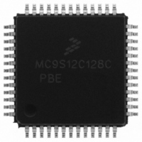
MC9S12C128CPBE Freescale Semiconductor, MC9S12C128CPBE Datasheet - Page 162

MC9S12C128CPBE
Manufacturer Part Number
MC9S12C128CPBE
Description
IC MCU 128K FLASH 25MHZ 52-LQFP
Manufacturer
Freescale Semiconductor
Series
HCS12r
Specifications of MC9S12C128CPBE
Core Processor
HCS12
Core Size
16-Bit
Speed
25MHz
Connectivity
CAN, EBI/EMI, SCI, SPI
Peripherals
POR, PWM, WDT
Number Of I /o
35
Program Memory Size
128KB (128K x 8)
Program Memory Type
FLASH
Ram Size
4K x 8
Voltage - Supply (vcc/vdd)
2.35 V ~ 5.5 V
Data Converters
A/D 8x10b
Oscillator Type
Internal
Operating Temperature
-40°C ~ 85°C
Package / Case
52-LQFP
Lead Free Status / RoHS Status
Lead free / RoHS Compliant
Eeprom Size
-
Available stocks
Company
Part Number
Manufacturer
Quantity
Price
Company:
Part Number:
MC9S12C128CPBE
Manufacturer:
Freescale Semiconductor
Quantity:
10 000
Company:
Part Number:
MC9S12C128CPBER
Manufacturer:
Freescale Semiconductor
Quantity:
10 000
- Current page: 162 of 690
- Download datasheet (4Mb)
Chapter 5 Interrupt (INTV1) Block Description
5.4.1
The INT does not contain any user-controlled options for reducing power consumption. The operation of
the INT in low-power modes is discussed in the following subsections.
5.4.1.1
The INT does not contain any options for reducing power in run mode.
5.4.1.2
Clocks to the INT can be shut off during system wait mode and the asynchronous interrupt path will be
used to generate the wake-up signal upon recognition of a valid interrupt or any XIRQ request.
5.4.1.3
Clocks to the INT can be shut off during system stop mode and the asynchronous interrupt path will be
used to generate the wake-up signal upon recognition of a valid interrupt or any XIRQ request.
5.5
The INT supports three system reset exception request types: normal system reset or power-on-reset
request, crystal monitor reset request, and COP watchdog reset request. The type of reset exception request
must be decoded by the system and the proper request made to the core. The INT will then provide the
service routine address for the type of reset requested.
5.6
As shown in the block diagram in
and control, an optional highest priority I interrupt (HPRIO) block, and a priority decoder to evaluate
whether pending interrupts are valid and assess their priority.
5.6.1
The INT registers are accessible only in special modes of operation and function as described in
Section 5.3.2.1, “Interrupt Test Control
previously.
5.6.2
When the optional HPRIO block is implemented, the user is allowed to promote a single I-bit maskable
interrupt to be the highest priority I interrupt. The HPRIO evaluates all interrupt exception requests and
passes the HPRIO vector to the priority decoder if the highest priority I interrupt is active. RTI replaces
the promoted interrupt source.
162
Resets
Interrupts
Low-Power Modes
Interrupt Registers
Highest Priority I-Bit Maskable Interrupt
Operation in Run Mode
Operation in Wait Mode
Operation in Stop Mode
Figure
MC9S12C-Family / MC9S12GC-Family
Register,” and
5-1, the INT contains a register block to provide interrupt status
Rev 01.24
Section 5.3.2.2, “Interrupt Test
Freescale Semiconductor
Registers,”
Related parts for MC9S12C128CPBE
Image
Part Number
Description
Manufacturer
Datasheet
Request
R
Part Number:
Description:
Manufacturer:
Freescale Semiconductor, Inc
Datasheet:
Part Number:
Description:
Manufacturer:
Freescale Semiconductor, Inc
Datasheet:
Part Number:
Description:
Manufacturer:
Freescale Semiconductor, Inc
Datasheet:
Part Number:
Description:
Manufacturer:
Freescale Semiconductor, Inc
Datasheet:
Part Number:
Description:
Manufacturer:
Freescale Semiconductor, Inc
Datasheet:
Part Number:
Description:
Manufacturer:
Freescale Semiconductor, Inc
Datasheet:
Part Number:
Description:
Manufacturer:
Freescale Semiconductor, Inc
Datasheet:
Part Number:
Description:
Manufacturer:
Freescale Semiconductor, Inc
Datasheet:
Part Number:
Description:
Manufacturer:
Freescale Semiconductor, Inc
Datasheet:
Part Number:
Description:
Manufacturer:
Freescale Semiconductor, Inc
Datasheet:
Part Number:
Description:
Manufacturer:
Freescale Semiconductor, Inc
Datasheet:
Part Number:
Description:
Manufacturer:
Freescale Semiconductor, Inc
Datasheet:
Part Number:
Description:
Manufacturer:
Freescale Semiconductor, Inc
Datasheet:
Part Number:
Description:
Manufacturer:
Freescale Semiconductor, Inc
Datasheet:
Part Number:
Description:
Manufacturer:
Freescale Semiconductor, Inc
Datasheet:


