ZUP/NC401 TDK Corporation, ZUP/NC401 Datasheet - Page 19
ZUP/NC401
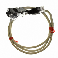
Manufacturer Part Number
ZUP/NC401
Description
CABLE COMMUNICATIONS RS232
Manufacturer
TDK Corporation
Series
ZUPr
Specifications of ZUP/NC401
Connector Type
D-Sub 09 pos Male to RS232 8 pos Male
Length
3.28' (1.00m)
Cable Type
Round
Color
White
Shielding
Shielded
Usage
Communication
Cable Length
1m
Connector Type B
RJ45
Connector Type A
DB9 Female
Cable Assembly Type
Serial
For Use With
ZUP Series Power Supplies
Lead Free Status / RoHS Status
Lead free / RoHS Compliant
Other names
285-1666


This power supply is equipped with a three conductor power cable. The third conductor is the ground
conductor. When the cable is plugged-in to an appropriate receptacle, the power supply is grounded.
Under no circumstances should this power supply be operated without an adequate ground
connection. If a two contact receptacle is encountered, it must be replaced by a three contact
receptacle, properly grounded. This operation should be done by a qualified electrician. It is
recommended to keep the AC input wires separate from the DC output and signal wires to avoid
interference.
To meet radiated EMI specification, the EMI suppressor clamp should be attached to the AC cable as
close as possible to the AC inlet of the power supply.
3.7 CONNECTING THE LOAD
Turn off the AC input power before making or changing any rear panel connection.
Make sure that all connections are securely tightened before applying power.
There is a potential shock hazard when using a power supply with a rated output greater than 40V.
Use load wiring with a minimum insulation rating equivalent to the maximum output voltage of the
power supply.
3.7.1 Selecting wire size
Two factors must be considered in selecting wire size.
1. Wires should be at least heavy enough to avoid overheating while carrying the power supply load
current at the rated load, or the current that would flow in the event the load wire were shorted,
whichever is greater.
2. Wire size should be selected to enable voltage drop per lead to be less than 0.5V at the rated current.
It is recommended to minimize voltage drop on the wires to prevent excessive output power
consumption from the power supply.
Please refer to Tables 3-1 and 3-2 for maximum wire length to limit voltage drop by American and
European measurements respectively.
14
12
10
8
6
4
2
0
2.526
1.589
0.9994
0.6285
0.3953
0.2486
0.1564
0.0983
Some components inside the power supply are at AC voltage even when the
On/Off switch is in the “Off” position. To avoid the hazard of electric shock,
disconnect line cord and load and wait 2 minutes before removing cover.
1016
100
160
253
400
640
5A
Maximum length in feet -
to limit voltage drop to 0.5V or less
40
63
10A
126
200
320
508
20
31
50
80
20A
100
160
254
10
15
25
40
63
WARNING
WARNING
50A
102
10
16
25
40
64
4
6
150A
1.7
13
21
34
1
3
5
8
Table 3-1: Maximum wire length for
0.5V drop on lead (in feet)
Related parts for ZUP/NC401
Image
Part Number
Description
Manufacturer
Datasheet
Request
R

Part Number:
Description:
TDK DC to DC Converters, DC to AC Inverters
Manufacturer:
TDK Corporation
Datasheet:
Part Number:
Description:
TDK DC to DC Converters, DC to AC Inverters
Manufacturer:
TDK Corporation
Datasheet: