ZUP/NC401 TDK Corporation, ZUP/NC401 Datasheet - Page 32
ZUP/NC401
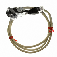
Manufacturer Part Number
ZUP/NC401
Description
CABLE COMMUNICATIONS RS232
Manufacturer
TDK Corporation
Series
ZUPr
Specifications of ZUP/NC401
Connector Type
D-Sub 09 pos Male to RS232 8 pos Male
Length
3.28' (1.00m)
Cable Type
Round
Color
White
Shielding
Shielded
Usage
Communication
Cable Length
1m
Connector Type B
RJ45
Connector Type A
DB9 Female
Cable Assembly Type
Serial
For Use With
ZUP Series Power Supplies
Lead Free Status / RoHS Status
Lead free / RoHS Compliant
Other names
285-1666


4.3.4 Constant Current check
4.3.5 OVP check
Turn off the power supply. Connect an electronic load with suitable voltage and current rating to the
output terminals, as explained in paragraph 3.7.3. Turn-on the power supply. Vary the load current and
check that the unit regulates the output voltage while the load current is smaller than the power supply
current rating. Further increase the load current and check that the power supply regulates the output
current.
Adjust the output voltage to zero using the front panel knob. Momentarily press OVP/UVP pushbutton
until the OVP LED illuminates and the VOLTS display shows OUP. The AMPS display will show the last
setting of the OVP level. Rotate the Adjust knob to 50% of the supply’s voltage rating. Adjust the output
voltage toward it’s maximum and check that the output voltage cannot be increased more than the OVP
setting.
4.3.6 UVP check
4.3.7 Foldback check
4.3.8 Output On/Off
4.3.9 Address setting
4.3.10 Local/Remote operation
Adjust the output voltage to the rated voltage using the front panel knob. Momentarily press OVP/UVP
pushbutton until the UVP LED illuminates and the VOLTS display shows UUP.. The AMPS display will
show the last setting of the UVP level. Rotate the ADJUST knob to 50% of the supply’s voltage rating.
Adjust the output voltage toward it’s minimum and check that the output voltage cannot be decreased
below the UVP setting.
Set the load current to 50% of the supply rating. Momentarily press FOLD pushbutton and check that
the FOLD LED illuminates. Increase the load current toward the supply current rating. Check that the
output voltage and current fall to zero when the load current reaches the Constant Current setting. The
FOLD LED should flash , the ALM LED illuminates and the output is disabled in this condition.
Reduce the load current setting below the power supply current rating and momentarily press FOLD
pushbutton. Check that the output voltage and current recover and FOLD continuously illuminates.
Momentarily press the FOLD pushbutton and check that FOLD LED turns off.
Repeatedly press OUT pushbutton and check that the power supply output is turned On and Off. While
the output is On, the OUT LED illuminates. While the output is Off, the LED is Off.
Momentarily press ADDR pushbutton so the ADDR LED illuminates and the AMPS display shows Addr.
The VOLTS display shows the last address setting. Rotate the ADJUST knob and check that the
VOLTS display varies between 0 and 31.
Repeatedly press REM pushbutton and check that REM LED turns on and off. While the power supply
is at Remote mode, the LED is on and while at Local mode, the LED is off. While the LED is off, turn off
the power supply, remove the DVM and the load wires.
Related parts for ZUP/NC401
Image
Part Number
Description
Manufacturer
Datasheet
Request
R

Part Number:
Description:
TDK DC to DC Converters, DC to AC Inverters
Manufacturer:
TDK Corporation
Datasheet:
Part Number:
Description:
TDK DC to DC Converters, DC to AC Inverters
Manufacturer:
TDK Corporation
Datasheet: