ZUP/NC401 TDK Corporation, ZUP/NC401 Datasheet - Page 36
ZUP/NC401
Manufacturer Part Number
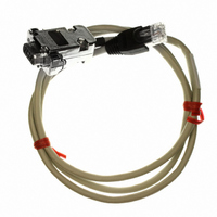
ZUP/NC401
Description
CABLE COMMUNICATIONS RS232
Manufacturer
TDK Corporation
Series
ZUPr
Specifications of ZUP/NC401
Connector Type
D-Sub 09 pos Male to RS232 8 pos Male
Length
3.28' (1.00m)
Cable Type
Round
Color
White
Shielding
Shielded
Usage
Communication
Cable Length
1m
Connector Type B
RJ45
Connector Type A
DB9 Female
Cable Assembly Type
Serial
For Use With
ZUP Series Power Supplies
Lead Free Status / RoHS Status
Lead free / RoHS Compliant
Other names
285-1666


4.4.9 Last Setting Memory
The ZUP series is equipped with Last Setting Memory which stores all power supply parameters at
each ac turn-off sequence of the power supply. The OUT parameter storage is determined prior to the
ac turn-off to allow two modes of re-start of the power supply.
STORED PARAMETERS
1. Automatic start mode
In this mode the power supply restores it’s last operation setting and sets the OUT to ‘ON’ state. Upon
start-up, the output is enabled and the power supply delivers power to the output terminals. To select
this mode press and hold OUT pushbutton. After approx. 3sec., the display will continuously cycle
between AS ON (auto-start on) and AS OFF (auto-start off), approx. every 3sec. Releasing the OUT
pushbutton while AS ON is displayed, will set the power supply to automatic start mode. (holding OUT
depressed for more than 1sec. does not change the output on/off status). In cases where the Over
Voltage or Over Temperature or Foldback protection has been activated , the unit will automatically
change to safe start mode after the AC voltage recycling.
1. For resistive programming, internal current sources, for output voltage and/or output current control,
2. To maintain the temperature stability specification of the power supply, the resistors used for
3. Where external resistor programming is used, front panel control and computer control (via serial
2. Safe start mode
4.4.10 Output Voltage & Current programming
In this mode, the power supply restores it’s last operation setting and sets the OUT to the ‘OFF’ state. To
select this mode, press and hold OUT pushbutton. After approx. 3sec., the display will continuously
cycle between AS ON (auto-start on) and AS OFF (auto-start off), approx. every 3sec. Releasing the
OUT pushbutton while AS OFF is displayed will set the power supply to safe start mode. At startup, the
output is disabled and the output voltage and current are zero. To enable the output and restore the last
output voltage and current values, OUT pushbutton should be momentarily pressed.
1. Output Voltage
2. Output Current
3. OVP Levels
4. UVP Levels
5. FOLD
6. Re-start mode
A variable resistor can control the output over it’s entire range, or a combination of variable resistor
supply 1mA current through external programming resistors. The voltage across the programming
resistors is used as a programming voltage for the power supply. Resistance of 0~4kohm programs
and series/parallel resistors can control the output over a restricted portion of it’s range. Alternatively,
a switch can be used to select fixed values of programming resistance to obtain a set of discrete
voltages or currents. Care must be taken to avoid open circuit at the programming resistors, as it will
cause over-voltage at the output. In this case, no damage to the power supply will be caused
however, it is recommended to set OVP limit to a level which is safe for the load circuitry.
programming should be stable and low noise resistors, with temperature coefficient of less than
25ppm and power rating of 1/4W or more.
communication) of the output voltage and current are disabled.
the output from 0 to full scale (full scale is 105% of the rated voltage or current).
by external resistor
10. Baud-rate
11. Service request parameters
(Items 8-10 are related to computer controlled
operation and explained in chapter 5).
7. REMOTE/LOCAL
8. ADDRESS
9. Communication Standard (RS232/RS485)
Related parts for ZUP/NC401
Image
Part Number
Description
Manufacturer
Datasheet
Request
R

Part Number:
Description:
TDK DC to DC Converters, DC to AC Inverters
Manufacturer:
TDK Corporation
Datasheet:
Part Number:
Description:
TDK DC to DC Converters, DC to AC Inverters
Manufacturer:
TDK Corporation
Datasheet: