ZUP/NC401 TDK Corporation, ZUP/NC401 Datasheet - Page 44
ZUP/NC401
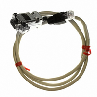
Manufacturer Part Number
ZUP/NC401
Description
CABLE COMMUNICATIONS RS232
Manufacturer
TDK Corporation
Series
ZUPr
Specifications of ZUP/NC401
Connector Type
D-Sub 09 pos Male to RS232 8 pos Male
Length
3.28' (1.00m)
Cable Type
Round
Color
White
Shielding
Shielded
Usage
Communication
Cable Length
1m
Connector Type B
RJ45
Connector Type A
DB9 Female
Cable Assembly Type
Serial
For Use With
ZUP Series Power Supplies
Lead Free Status / RoHS Status
Lead free / RoHS Compliant
Other names
285-1666


5.1
This chapter describes the operation of the ZUP series via the serial communication port. details of the
initial set-up, operation via RS232 or RS485, the command set and the communication protocol are
described in this chapter.
5.2
5.2.1 Address setting
The ZUP addresses can be set to any address between 01 and 31. Follow the procedure described
below to set the address.
1. Momentarily press the ADDR pushbutton on the front panel so the ADDR LED illuminates and the
2. Rotate the front panel knob. While rotating the knob the AMPS display will show the selected
3. While the unit is in operation, depressing the ADDR pushbutton will cause the display to show the
5.2.2 RS232 or RS485 selection
To select between RS232 or RS485 serial communication the following steps should be taken.
1. Press and hold REM pushbutton.(holding REM depressed for more than 1sec does not change the
2. Press and hold REM pushbutton. After approx. 3sec. the display will continuously cycle between
3. To select RS232, release the REM pushbutton while ‘rs232 is displayed. To select RS485, release
4. Approx. 3sec after releasing the REM, the display returns to show the actual voltage and current.
5.2.3 Baud rate setting
Six optional rates are possible:300, 600, 1200, 2400, 4800, 9600. To select the desired rate, the
following steps should be taken. The power supply should be at Local operation mode during the
following procedure:
1. Press and hold ADDR pushbutton. After approx. 3 sec. the display will continuously cycle between
2. To select the desired rate, release ADDR while that rate is displayed.
3. After releasing ADDR the display will return to show the actual voltage and current.
5.2.4 Local/Remote selection
To enable the operation via RS232 or RS485, the power supply should be at Remote mode. At this
mode, all the front panel functions are disabled except Local/Remote pushbutton.
1. Via the front panel: Momentarily press REM pushbutton so the REM LED illuminates. To return from
2. Via the serial communication port (RS232/RS485): By sending a :RMTn; command to the power
Transition from Local to Remote control:
CHAPTER 5 RS232 & RS485 REMOTE CONTROL
VOLTS display shows ‘Addr’.
address. When the rotation is stopped, the address shown will be the selected address. The display
will return to show the actual voltage and current approx. 3 sec. from termination of rotating knob.
selected address.
local/remote status).
Remote to Local control, momentarily press REM pushbutton so the REM LED extinguishes.
supply. Refer to par. 5.5.2.
‘rs232’ and ‘rs485’ approx. every 3sec.
the REM pushbutton while ‘rs485 is displayed.
the six optional rates approx. every 2 seconds.
CONFIGURATION
INTRODUCTION
Related parts for ZUP/NC401
Image
Part Number
Description
Manufacturer
Datasheet
Request
R

Part Number:
Description:
TDK DC to DC Converters, DC to AC Inverters
Manufacturer:
TDK Corporation
Datasheet:
Part Number:
Description:
TDK DC to DC Converters, DC to AC Inverters
Manufacturer:
TDK Corporation
Datasheet: