ZUP/NC401 TDK Corporation, ZUP/NC401 Datasheet - Page 52
ZUP/NC401
Manufacturer Part Number
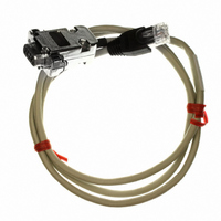
ZUP/NC401
Description
CABLE COMMUNICATIONS RS232
Manufacturer
TDK Corporation
Series
ZUPr
Specifications of ZUP/NC401
Connector Type
D-Sub 09 pos Male to RS232 8 pos Male
Length
3.28' (1.00m)
Cable Type
Round
Color
White
Shielding
Shielded
Usage
Communication
Cable Length
1m
Connector Type B
RJ45
Connector Type A
DB9 Female
Cable Assembly Type
Serial
For Use With
ZUP Series Power Supplies
Lead Free Status / RoHS Status
Lead free / RoHS Compliant
Other names
285-1666


2. Alarm Status Register:
The alarm status register records fault conditions occurring during power supply operation. Any set bit
in this register causes the ‘alarm’ bit in the operational status register to be set. Reading the register
does not change it’s content. The register is cleared by :DCL; command.
Table 5-6: Alarm status register content.
Notes: (*1) Since at each AC turn off the AC fail bit is generated and stored, it is recommended to
3. Error Codes Register:
The error codes register records errors that occurred during the programming of the power supply. Any
set bit in this register causes the ‘prog’ bit in the alarm status register to be set. Reading the register
does not change it’s content. The register is cleared by :DCL; command.
Table 5-7: Error codes register content.
5.5.4.2 Status control commands
Bit Name
ovp
otp
a/c fail
fold
prog
Bit Name
not used
wrong command
buffer overflow
wrong voltage
wrong current
2
#
1
Commands
:ALM?;
:STA?;
(*2) FOLD bit is automatically reset upon cancellation of FOLD protection.
(*3) OVP, OTP and ‘prog’ bits reset at AC turn-off or by :DCL; command.
send a :DCL; command following application of AC voltage to the power supply, to clear the
alarm status register.
In case the OTP or OVP is triggered, the front panel control is disabled until the AC input is
recycled by turning the AC ON/OFF switch to OFF and after approx. 10 sec. to ON.
Bit No
1
2
3
4
5
Bit No
1
2
3
4
5
‘1’ - Indicates that the over-voltage protection was tripped
‘1’ - Indicates that the over-temperature protection was tripped
‘1’ - Indicates that a failure occurred at the input voltage supply
‘1’ - Indicates that the foldback protection was activated
‘1’ - Indicates a programming error has occurred
Meaning
Reads the alarm status register content.
Returns the string AL followed by ASCII characters representing the
register’s content.
Refer to table 5-6 for the register content description.
example- AL00000
Reads the operational status register content.
Returns the string
register’s content.
Refer to table 5-5 for the register content description.
example- OS00010000
Description
‘1’ - Indicates that an unknown string was received
‘1’ - Indicates an overflow in the communication buffer
‘1’ - Indicates an attempt to program the power supply to a voltage
out of specification limits.
‘1’ - Indicates an attempt to program the power supply to a current
out of specification limits.
Meaning
OS
followed by ASCII characters representing the
(*3)
(*3)
(*1)
(*2)
(*3)
Related parts for ZUP/NC401
Image
Part Number
Description
Manufacturer
Datasheet
Request
R

Part Number:
Description:
TDK DC to DC Converters, DC to AC Inverters
Manufacturer:
TDK Corporation
Datasheet:
Part Number:
Description:
TDK DC to DC Converters, DC to AC Inverters
Manufacturer:
TDK Corporation
Datasheet: