ZUP/NC401 TDK Corporation, ZUP/NC401 Datasheet - Page 33
ZUP/NC401
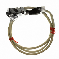
Manufacturer Part Number
ZUP/NC401
Description
CABLE COMMUNICATIONS RS232
Manufacturer
TDK Corporation
Series
ZUPr
Specifications of ZUP/NC401
Connector Type
D-Sub 09 pos Male to RS232 8 pos Male
Length
3.28' (1.00m)
Cable Type
Round
Color
White
Shielding
Shielded
Usage
Communication
Cable Length
1m
Connector Type B
RJ45
Connector Type A
DB9 Female
Cable Assembly Type
Serial
For Use With
ZUP Series Power Supplies
Lead Free Status / RoHS Status
Lead free / RoHS Compliant
Other names
285-1666


4.4
4.4.1 Introduction
4.4.2 Constant Voltage Operation
4. For fine adjustment of output voltage, press V/A consecutively until the V LED illuminates and the
4. For fine adjustment of output current, press V/A consecutively until the A LED illuminates and the
This paragraph describes the operating modes not involved in programming the power supply via it’s
serial communication port. Operation utilizing the front and rear panel are described in this paragraph.
For information regarding serial port usage, please refer to chapter 5.
The REM LED on the front panel indicates whether the power supply is in Local or Remote mode. The
extinguished LED indicates Local operation. If the LED illuminates, the REM pushbutton (fig.4-1, item
8),should be pressed to change the operating mode to Local.
1. In constant voltage mode, the power supply maintains the output voltage at the selected value while
2. While the power supply is operating at constant voltage, the CV LED on the front panel illuminates.
3. For coarse output voltage adjustment, press V/A consecutively, until the V LED illuminates, and
3. For coarse output current adjustment, press V/A consecutively, until the A LED illuminates, and
The maximum and minimum setting values of the output voltage are limited by the over voltage and
1. In constant current mode the power supply maintains the output current at the selected value, while
2. While the power supply is operating at constant current, the CC LED on the front panel illuminates.
4.4.3 Constant Current Operation
supply may be at current limit. Check the load condition and the power supply current limit setting.
If after completing the adjustment the display shows a different value than the setting, the power
Approx 3sec. after the adjustment, the display returns to show the actual voltage and current.
Approx 3sec. after the adjustment, the display returns to show the actual voltage and current.
VOLTS display shows SL_V. The AMPS display will show the output voltage setting value. Rotate
the ADJUST knob to set the output voltage. At this mode the adjustment resolution is maximal.
VOLTS display shows SL_A. The AMPS display will show the output current setting value. Rotate
the ADJUST knob to set the output current. At this mode the adjustment resolution is maximal.
the load current varies as required by the load.
the load voltage varies with the load requirement.
the VOLTS display shows FA_V. The AMPS display will show the output voltage setting value.
Rotate the ADJUST knob to set the output voltage. At this mode, approx. 6 turns are required to
adjust the entire range. Approx. 3sec after the adjustment, the display returns to show the actual
voltage and current.
the VOLTS display shows FA_A. The AMPS display will show the output current setting value.
Rotate the ADJUST knob to set the output current. At this mode, approx. 6 turns are required to
adjust the entire range. Approx. 3sec after the adjustment, the display returns to show the actual
voltage and current.
LOCAL OPERATION
under voltage protection settings. Refer to par. 4.4.5 and 4.4.6 for details.
NOTE
NOTE
Related parts for ZUP/NC401
Image
Part Number
Description
Manufacturer
Datasheet
Request
R

Part Number:
Description:
TDK DC to DC Converters, DC to AC Inverters
Manufacturer:
TDK Corporation
Datasheet:
Part Number:
Description:
TDK DC to DC Converters, DC to AC Inverters
Manufacturer:
TDK Corporation
Datasheet: