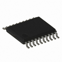
AT86RF401U-XI Atmel, AT86RF401U-XI Datasheet - Page 34

AT86RF401U-XI
Manufacturer Part Number
AT86RF401U-XI
Description
IC MICRO TX RF W/AVR 20-TSSOP
Manufacturer
Atmel
Datasheet
1.AT86RF401U-6GS.pdf
(52 pages)
Specifications of AT86RF401U-XI
Frequency
264MHz ~ 456MHz
Applications
Garage Opener, RKE, Telemetry
Modulation Or Protocol
ASK, OOK
Data Rate - Maximum
10 kbps
Power - Output
6dBm
Current - Transmitting
23.2mA
Data Interface
PCB, Surface Mount
Antenna Connector
PCB, Surface Mount
Memory Size
2KB Flash, 128 Byte EEPROM, 128Byte SRAM
Voltage - Supply
2 V ~ 5 V
Operating Temperature
-40°C ~ 85°C
Package / Case
20-TSSOP
Lead Free Status / RoHS Status
Contains lead / RoHS non-compliant
Features
-
Other names
AT86RF401U
34
AT86RF401
• Bit[5:3]: ULC[2:0]
The unlock count (ULC) bits count a certain number of reference clocks, after which the
unlock detect circuit looks for a number of cycle slips determined by CS[1:0] before
making the loc detect signal go low. The ULC bits essentially control the blackout period
of the unlock detect circuit. The unlock counter is reset by the KEY signal rising (if
ENKO is asserted), or by the LOC rising edge, or by the UPOK signal being set high.
Table 14. PLL Unlock Counter Definition
• Bits[2:0]: LC[2:0]
The Lock Count (LC) bits control a counter that, after a number of reference clocks,
cause lock detect to go high. This counter will reset if a cycle slip or a reset signal occurs
(which happens if TXE goes low), if an out-of-lock condition occurs, if the crystal oscilla-
tor frequency is too low, or if the VCO feedback frequency is too low.
Table 15. PLL Lock Counter Definition
ULC[2:0]
LC[2:0]
000
001
010
011
100
101
110
111
000
001
010
011
100
101
110
111
Number of REF Clocks of Delay
Clocks of Delay
Number of REF
1024
1024
128
256
512
128
256
512
16
32
64
16
32
64
8
8
1424F–RKE–12/03


