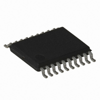
AT86RF401U-XI Atmel, AT86RF401U-XI Datasheet - Page 42

AT86RF401U-XI
Manufacturer Part Number
AT86RF401U-XI
Description
IC MICRO TX RF W/AVR 20-TSSOP
Manufacturer
Atmel
Datasheet
1.AT86RF401U-6GS.pdf
(52 pages)
Specifications of AT86RF401U-XI
Frequency
264MHz ~ 456MHz
Applications
Garage Opener, RKE, Telemetry
Modulation Or Protocol
ASK, OOK
Data Rate - Maximum
10 kbps
Power - Output
6dBm
Current - Transmitting
23.2mA
Data Interface
PCB, Surface Mount
Antenna Connector
PCB, Surface Mount
Memory Size
2KB Flash, 128 Byte EEPROM, 128Byte SRAM
Voltage - Supply
2 V ~ 5 V
Operating Temperature
-40°C ~ 85°C
Package / Case
20-TSSOP
Lead Free Status / RoHS Status
Contains lead / RoHS non-compliant
Features
-
Other names
AT86RF401U
Button Detect Register – B_DET
Battery Low Configuration Register – BL_CONFIG
42
Initial Value
Initial Value
Read/Write
Read/Write
AT86RF401
$34
$35
Bit
Bit
BL
R
R
7
–
0
7
0
code execution at the reset location. This bit is reset at POR and when exiting the button
reset state. All other registers remain unchanged.
• Bits[7:6]
Reserved. These bits read “0”.
• Bits[5:0]
When an I/O pin is configured as a button using the IO_ENAB and IO_DATOUT regis-
ters and a logic low is detected on that pin, the button detect logic is activated. If the part
is in sleep mode, the part responds as described in the AVR Configuration Register
description. If a good battery is present, the appropriate bit is set in this register. A bit in
this register is cleared by writing a “0” to it.
• Bit[7]: Battery Low
When Bit[6] in this register is set (Battery Low Valid), the BL (Battery Low) bit indicates
that the battery voltage is lower than the voltage level that is determined by Bit[5:0] of
this register. It is important that the programmer also check Bit[6] (Battery Low Valid) to
be certain that this condition is valid.
• Bit[6]: Battery Low Valid
When the Battery Low Configuration Register is written, this bit is set to “0”. When the
battery voltage has been sampled and compared to the voltage determined by the BLx
bits, this bit is set to “1” indicating that the data in Bit[7] (Battery Low) is valid. This can
take up to 3100 XTAL cycles to complete.
Note:
• Bit[5:0]: Battery Low Detection Level
This value is sent to the battery monitor. The threshold is calculated using the formulas
shown in Table 21 on page 43.
Note:
BLV
R
R
6
–
0
6
0
The programmer should ensure that this bit is cleared prior to making a determination of
the Battery Low status. This can be done by reloading Bit[5] or directly clearing Bit[6].
Generally, the programmer loads Bit[5], loops until Bit[6] is set, and then checks Bit[3] to
determine the status of the battery.
This threshold can be set below the brown-out voltage level.
BD5
R/W
R/W
BL5
5
0
5
0
BD4
R/W
R/W
BL4
4
0
4
0
BD3
R/W
R/W
BL3
3
0
3
0
BD2
R/W
R/W
BL2
2
0
2
0
BD1
R/W
R/W
BL1
1
0
1
0
1424F–RKE–12/03
BD0
R/W
R/W
BL0
0
0
0
0


