APT100GT60JRDQ4 Microsemi Power Products Group, APT100GT60JRDQ4 Datasheet - Page 4
APT100GT60JRDQ4
Manufacturer Part Number
APT100GT60JRDQ4
Description
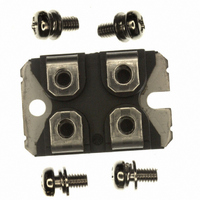
IGBT 600V 148A 500W SOT227
Manufacturer
Microsemi Power Products Group
Series
Thunderbolt IGBT®r
Datasheet
1.APT100GT60JRDQ4.pdf
(9 pages)
Specifications of APT100GT60JRDQ4
Igbt Type
NPT
Configuration
Single
Voltage - Collector Emitter Breakdown (max)
600V
Vce(on) (max) @ Vge, Ic
2.5V @ 15V, 100A
Current - Collector (ic) (max)
148A
Current - Collector Cutoff (max)
50µA
Input Capacitance (cies) @ Vce
5.15nF @ 25V
Power - Max
500W
Input
Standard
Ntc Thermistor
No
Mounting Type
Chassis Mount
Package / Case
ISOTOP
Lead Free Status / RoHS Status
Lead free / RoHS Compliant
Other names
APT100GT60JRDQ4MI
APT100GT60JRDQ4MI
APT100GT60JRDQ4MI
Available stocks
Company
Part Number
Manufacturer
Quantity
Price
Company:

Part Number:
APT100GT60JRDQ4
Manufacturer:
Microsemi Power Products Group
Quantity:
135


Typical Performance Curves
FIGURE 15, Switching Energy Losses vs. Gate Resistance
16000
14000
12000
10000
35000
30000
25000
20000
15000
10000
8000
6000
4000
2000
5000
FIGURE 13, Turn-On Energy Loss vs Collector Current
250
200
150
100
FIGURE 11, Current Rise Time vs Collector Current
FIGURE 9, Turn-On Delay Time vs Collector Current
35
30
25
20
15
10
50
5
0
0
0
0
I
I
CE
CE
I
0
0
0
0
CE
V
V
T
V
T
R
L = 100µH
V
V
R
, COLLECTOR TO EMITTER CURRENT (A)
, COLLECTOR TO EMITTER CURRENT (A)
CE
GE
J
R
CE
GE
J
G
CE
G
, COLLECTOR TO EMITTER CURRENT (A)
= 125°C
G
= 25°C
= 4.3Ω
25
25
25
= 4.3Ω
= 400V
= +15V
= 400V
= +15V
= 400V
=
R
4.3Ω, L
G
E
10
, GATE RESISTANCE (OHMS)
50
50
50
off,
,
or 125°C
200A
V
GE
75 100 125 150 175 200 225
=
75 100 125 150 175 200 225
75 100 125 150 175 200 225
100
T
= 15V
20
T
J
E
µ
J
=
H, V
on2,
=
25 or 125°C,V
125°C
T
50A
CE
E
J
on2,
=
=
30
25°C
100A
400V
E
off,
50A
E
GE
on2,
40
=
200A
E
15V
off,
100A
50
FIGURE 16, Switching Energy Losses vs Junction Temperature
12000
10000
16000
14000
12000
10000
FIGURE 14, Turn Off Energy Loss vs Collector Current
8000
6000
4000
2000
8000
6000
4000
2000
450
400
350
300
250
200
150
100
FIGURE 10, Turn-Off Delay Time vs Collector Current
200
180
160
140
120
100
FIGURE 12, Current Fall Time vs Collector Current
50
80
60
40
20
0
0
0
0
I
I
CE
CE
I
0
0
0
0
CE
V
V
R
V
V
R
E
E
V
R
L = 100µH
E
, COLLECTOR TO EMITTER CURRENT (A)
, COLLECTOR TO EMITTER CURRENT (A)
R
CE
GE
G
CE
GE
G
on2,
off,
CE
G
, COLLECTOR TO EMITTER CURRENT (A)
off,
V
G
= 4.3Ω
= 4.3Ω
25
25
25
GE
=
= 400V
= 400V
= +15V
50A
T
= +15V
=
200A
=
100A
J
4.3Ω
=15V,T
400V
4.3Ω, L
, JUNCTION TEMPERATURE (°C)
T
25
50
50
50
J
T
=
J
125°C, V
J
=
=25°C
=
75 100 125 150 175 200 225
75 100 125 150 175 200 225
70 100 125 150 175 200 225
25°C, V
100
E
50
on2,
µ
H, V
GE
50A
GE
T
V
J
T
=
CE
GE
J
=
=
15V
=
125°C
=
=15V,T
15V
E
75
25°C
on2,
400V
APT100GT60JRDQ4
200A
J
=125°C
100
E
off,
100A
125
Related parts for APT100GT60JRDQ4
Image
Part Number
Description
Manufacturer
Datasheet
Request
R

Part Number:
Description:
IGBT 600V 100A 463W TO247
Manufacturer:
Microsemi Power Products Group
Datasheet:

Part Number:
Description:
IGBT 600V 198A 833W TO264
Manufacturer:
Microsemi Power Products Group
Datasheet:
Part Number:
Description:
IGBT 600V 41A 187W TO247
Manufacturer:
Microsemi Power Products Group
Datasheet:
Part Number:
Description:
MOSFET N-CH 600V 23A TO-247
Manufacturer:
Microsemi Power Products Group
Datasheet:

Part Number:
Description:
MOSFET N-CH 500V 17A TO-220
Manufacturer:
Microsemi Power Products Group
Datasheet:
Part Number:
Description:
MOSFET N-CH 1200V 3.5A TO-220
Manufacturer:
Microsemi Power Products Group
Datasheet:
Part Number:
Description:
MOSFET N-CH 500V 22A TO-247
Manufacturer:
Microsemi Power Products Group
Datasheet:
Part Number:
Description:
MOSFET N-CH 100V 75A TO-247
Manufacturer:
Microsemi Power Products Group
Datasheet:
Part Number:
Description:
MOSFET N-CH 200V 56A TO-247
Manufacturer:
Microsemi Power Products Group
Datasheet:
Part Number:
Description:
MOSFET N-CH 500V 27A TO-247
Manufacturer:
Microsemi Power Products Group
Datasheet:
Part Number:
Description:
MOSFET N-CH 300V 40A TO-247
Manufacturer:
Microsemi Power Products Group
Datasheet:
Part Number:
Description:
MOSFET N-CH 200V 59A TO-247
Manufacturer:
Microsemi Power Products Group
Datasheet:
Part Number:
Description:
MOSFET N-CH 500V 26A TO-247
Manufacturer:
Microsemi Power Products Group
Datasheet:
Part Number:
Description:
MOSFET N-CH 300V 40A TO-247
Manufacturer:
Microsemi Power Products Group
Datasheet:
Part Number:
Description:
MOSFET N-CH 200V 65A TO-247
Manufacturer:
Microsemi Power Products Group
Datasheet: