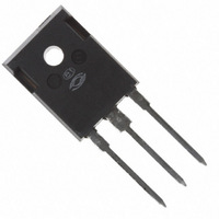
APT20M36BFLLG Microsemi Power Products Group, APT20M36BFLLG Datasheet

APT20M36BFLLG
Specifications of APT20M36BFLLG
Available stocks
Related parts for APT20M36BFLLG
APT20M36BFLLG Summary of contents
Page 1
POWER MOS 7 ® Power MOS new generation of low loss, high voltage, N-Channel enhancement mode power MOSFETS. Both conduction and switching losses are addressed with Power MOS 7 ® and Q . Power MOS 7 combines ...
Page 2
DYNAMIC CHARACTERISTICS Symbol Characteristic C Input Capacitance iss C Output Capacitance oss C Reverse Transfer Capacitance rss Q 3 Total Gate Charge g Q Gate-Source Charge gs Q Gate-Drain ("Miller ") Charge gd t Turn-on Delay Time d(on) t Rise ...
Page 3
RC MODEL Junction temp. (°C) 0.0329 Power 0.158 (watts) 0.189 Case temperature. (°C) FIGURE 2, TRANSIENT THERMAL IMPEDANCE MODEL 140 V DS > (ON (ON)MAX. 250µSEC. PULSE TEST 120 @ <0.5 % DUTY CYCLE 100 ...
Page 4
OPERATION HERE LIMITED (ON) 100 =+25° =+150°C SINGLE PULSE 100 V , DRAIN-TO-SOURCE VOLTAGE (VOLTS) DS FIGURE 10, MAXIMUM SAFE OPERATING AREA 16 I ...
Page 5
Typical Performance Curves 10% t d(on Drain Current 90 10% Drain Voltage Switching Energy Figure 18, Turn-on Switching Waveforms and Definitions APT60DS30 D.U.T. Figure 20, Inductive Switching Test Circuit ...


