APT50GF120JRDQ3 Microsemi Power Products Group, APT50GF120JRDQ3 Datasheet - Page 9
APT50GF120JRDQ3
Manufacturer Part Number
APT50GF120JRDQ3
Description
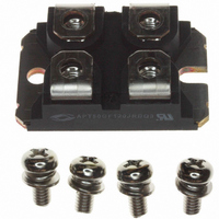
IGBT 1200V 120A 521W SOT227
Manufacturer
Microsemi Power Products Group
Datasheet
1.APT50GF120JRDQ3.pdf
(9 pages)
Specifications of APT50GF120JRDQ3
Igbt Type
NPT
Configuration
Single
Voltage - Collector Emitter Breakdown (max)
1200V
Vce(on) (max) @ Vge, Ic
3V @ 15V, 75A
Current - Collector (ic) (max)
120A
Current - Collector Cutoff (max)
750µA
Input Capacitance (cies) @ Vce
5.32nF @ 25V
Power - Max
521W
Input
Standard
Ntc Thermistor
No
Mounting Type
Chassis Mount
Package / Case
ISOTOP
Lead Free Status / RoHS Status
Lead free / RoHS Compliant
Other names
APT50GF120JRDQ3MI
APT50GF120JRDQ3MI
APT50GF120JRDQ3MI
Available stocks
Company
Part Number
Manufacturer
Quantity
Price
Company:

Part Number:
APT50GF120JRDQ3
Manufacturer:
Microsemi Power Products Group
Quantity:
135
Company:
Part Number:
APT50GF120JRDQ3
Manufacturer:
APT
Quantity:
1 000
Part Number:
APT50GF120JRDQ3
Quantity:
122


ISOTOP
5,262,336 6 ,503,786 5 ,256,583 4 ,748,103 5 ,283,202 5 ,231,474 5 ,434,095 5 ,528,058 and foreign patents. US and Foreign patents pending. A ll Rights Reserved.
TYPICAL PERFORMANCE CURVES
1
4
5
2
3
I
di
I
t rr - Reverse R ecovery Time, measured from zero crossing where diode
Q rr - Area Under the Curve Defined by I
®
F
RRM
is a Registered Trademark of SGS Thomson.
F
- Forward Conduction Current
/dt - Rate of Diode Current Change Through Zero Crossing.
line through I
r = 4.0 (.157)
current goes from positive to negative, to the point at which the straight
- Maximum Reverse Recovery Current.
+18V
(2 places)
0V
RRM
and 0.25 I
31.5 (1.240)
31.7 (1.248)
14.9 (.587)
15.1 (.594)
30.1 (1.185)
30.3 (1.193)
38.0 (1.496)
38.2 (1.504)
RRM
7.8 (.307)
8.2 (.322)
APT’s products are covered by one or more of U.S.patents 4,895,810 5 ,045,903 5 ,089,434 5 ,182,234 5 ,019,522
passes through zero.
SOT-227 (ISOTOP
Dimensions in Millimeters and (Inches)
Figure 33, Diode Reverse Recovery Waveform and Definitions
RRM
and t rr .
di
F
* Emitter/Anode
* Emitter/Anode
/dt Adjust
3.3 (.129)
3.6 (.143)
Figure 32. Diode Test Circuit
W=4.1 (.161)
W=4.3 (.169)
H=4.8 (.187)
H=4.9 (.193)
4.0 (.157)
4.2 (.165)
(2 places)
(4 places)
®
) Package Outline
30µH
Zero
V r
APT10035LLL
1
1.95 (.077)
2.14 (.084)
TRANSFORMER
PEARSON 2878
CURRENT
8.9 (.350)
9.6 (.378)
11.8 (.463)
12.2 (.480)
0.75 (.030)
0.85 (.033)
2
Collector/Cathode
D.U.T.
Gate
Hex Nut M4
*
(4 places)
Emitter/Anode terminals are
shorted internally. Current
handling capability is equal
for either Emitter/Anode terminal.
12.6 (.496)
12.8 (.504)
3
4
5
APT50GF120JRDQ3
25.2 (0.992)
25.4 (1.000)
t rr / Q rr
Waveform
0.25 I RRM
Related parts for APT50GF120JRDQ3
Image
Part Number
Description
Manufacturer
Datasheet
Request
R

Part Number:
Description:
IGBT 600V 100A 463W TO247
Manufacturer:
Microsemi Power Products Group
Datasheet:

Part Number:
Description:
IGBT 600V 198A 833W TO264
Manufacturer:
Microsemi Power Products Group
Datasheet:
Part Number:
Description:
IGBT 600V 41A 187W TO247
Manufacturer:
Microsemi Power Products Group
Datasheet:
Part Number:
Description:
MOSFET N-CH 600V 23A TO-247
Manufacturer:
Microsemi Power Products Group
Datasheet:

Part Number:
Description:
MOSFET N-CH 500V 17A TO-220
Manufacturer:
Microsemi Power Products Group
Datasheet:
Part Number:
Description:
MOSFET N-CH 1200V 3.5A TO-220
Manufacturer:
Microsemi Power Products Group
Datasheet:
Part Number:
Description:
MOSFET N-CH 500V 22A TO-247
Manufacturer:
Microsemi Power Products Group
Datasheet:
Part Number:
Description:
MOSFET N-CH 100V 75A TO-247
Manufacturer:
Microsemi Power Products Group
Datasheet:
Part Number:
Description:
MOSFET N-CH 200V 56A TO-247
Manufacturer:
Microsemi Power Products Group
Datasheet:
Part Number:
Description:
MOSFET N-CH 500V 27A TO-247
Manufacturer:
Microsemi Power Products Group
Datasheet:
Part Number:
Description:
MOSFET N-CH 300V 40A TO-247
Manufacturer:
Microsemi Power Products Group
Datasheet:
Part Number:
Description:
MOSFET N-CH 200V 59A TO-247
Manufacturer:
Microsemi Power Products Group
Datasheet:
Part Number:
Description:
MOSFET N-CH 500V 26A TO-247
Manufacturer:
Microsemi Power Products Group
Datasheet:
Part Number:
Description:
MOSFET N-CH 300V 40A TO-247
Manufacturer:
Microsemi Power Products Group
Datasheet:
Part Number:
Description:
MOSFET N-CH 200V 65A TO-247
Manufacturer:
Microsemi Power Products Group
Datasheet: