APT10M11JVRU2 Microsemi Power Products Group, APT10M11JVRU2 Datasheet

MOSFET N-CH 100V 142A SOT227

APT10M11JVRU2

Manufacturer Part Number
APT10M11JVRU2
Description
MOSFET N-CH 100V 142A SOT227
Manufacturer
Microsemi Power Products Group
Datasheet

Specifications of APT10M11JVRU2

Fet Type
MOSFET N-Channel, Metal Oxide
Fet Feature
Standard
Rds On (max) @ Id, Vgs
11 mOhm @ 71A, 10V
Drain To Source Voltage (vdss)
100V
Current - Continuous Drain (id) @ 25° C
142A
Vgs(th) (max) @ Id
4V @ 2.5mA
Gate Charge (qg) @ Vgs
300nC @ 10V
Input Capacitance (ciss) @ Vds
8600pF @ 25V
Power - Max
450W
Mounting Type
Chassis Mount
Package / Case
SOT-227, miniBLOC
Lead Free Status / RoHS Status
Lead free / RoHS Compliant
Other names
APT10M11JVRU2MI
APT10M11JVRU2MI

Available stocks

Company
Part Number
Manufacturer
Quantity
Price
Part Number:
APT10M11JVRU2
Manufacturer:
Microsemi Power Products Group
Quantity:
135
Absolute maximum ratings
Symbol
IF
R
V
IF
V
E
E
I
I
P
MOSFET Power Module
DSon
I
DM
ISOTOP
AR
RMS
DSS
AR
AS
D
GS
A V
D
Drain - Source Breakdown Voltage
Continuous Drain Current
Pulsed Drain current
Gate - Source Voltage
Drain - Source ON Resistance
Maximum Power Dissipation
Avalanche current (repetitive and non repetitive)
Repetitive Avalanche Energy
Single Pulse Avalanche Energy
Maximum Average Forward Current
RMS Forward Current (Square wave, 50% duty)
G
G
These Devices are sensitive to Electrostatic Discharge. Proper Handing Procedures Should Be Followed.
ISOTOP
S
®
Boost chopper
D
K
S
Parameter
K
D
www.microsemi.com
Duty cycle=0.5
Application
Features
Benefits
V
R
I
D
DSS
DSon
= 142A @ Tc = 25°C
AC and DC motor control
Switched Mode Power Supplies
Power Factor Correction
Brake switch
Power MOS V
ISOTOP
Very low stray inductance
High level of integration
Outstanding performance at high frequency operation
Direct mounting to heatsink (isolated package)
Low junction to case thermal resistance
Very rugged
Low profile
RoHS Compliant
= 100V
= 11mΩ max @ Tj = 25°C
-
-
-
-
-
-
T
T
T
Tc = 90°C
APT10M11JVRU2
c
c
c
= 25°C
= 80°C
= 25°C
®
Low R
Low input and Miller capacitance
Low gate charge
Fast intrinsic diode
Avalanche energy rated
Very rugged
Package (SOT-227)
®
DSon
MOSFETs
Max ratings
2500
±30
100
142
106
576
450
144
11
50
30
47
Unit
mΩ
mJ
W
V
A
V
A
A
1 – 7

Related parts for APT10M11JVRU2

APT10M11JVRU2 Summary of contents

Page 1

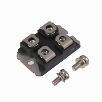
... AR E Single Pulse Avalanche Energy AS IF Maximum Average Forward Current RMS Forward Current (Square wave, 50% duty) RMS These Devices are sensitive to Electrostatic Discharge. Proper Handing Procedures Should Be Followed. APT10M11JVRU2 V = 100V DSS R = 11mΩ max @ Tj = 25°C DSon I = 142A @ Tc = 25°C D Application • ...

Page 2

... Reverse Recovery Time I Maximum Reverse Recovery Current RRM Q Reverse Recovery Charge rr t Reverse Recovery Time rr Q Reverse Recovery Charge rr I Maximum Reverse Recovery Current RRM APT10M11JVRU2 = 25°C unless otherwise specified j Test Conditions T = 25° 0V,V = 100V 125° 0V,V = 80V j ...

Page 3

... Storage Temperature Range J STG T Max Lead Temp for Soldering:0.063” from case for 10 sec L Torque Mounting torque (Mounting = 8-32 or 4mm Machine and terminals = 4mm Machine) Wt Package Weight Typical Performance Curve MOSFET APT10M11JVRU2 Min MOSFET Diode 2500 -55 www.microsemi.com Typ Max Unit 0.28 °C/W 1.21 20 ...

Page 4

... APT10M11JVRU2 www.microsemi.com 4 – 7 ...

Page 5

... Typical Diode Performance Curve APT10M11JVRU2 www.microsemi.com 5 – 7 ...

Page 6

... APT10M11JVRU2 www.microsemi.com 6 – 7 ...

Page 7

... Microsemi reserves the right to change, without notice, the specifications and information contained herein Microsemi's products are covered by one or more of U.S patents 4,895,810 5,045,903 5,089,434 5,182,234 5,019,522 5,262,336 6,503,786 5,256,583 4,748,103 5,283,202 5,231,474 5,434,095 5,528,058 and foreign patents. U.S and Foreign patents pending. All Rights Reserved. APT10M11JVRU2 W=4.1 (.161) W=4.3 (.169) H=4 ...

Related keywords