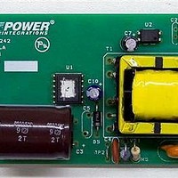
RDK-242 Power Integrations, RDK-242 Datasheet - Page 2

RDK-242
Manufacturer Part Number
RDK-242
Description
Power Management Modules & Development Tools TOPSwitch-JX REF. DESIGN KIT
Manufacturer
Power Integrations
Type
MOSFET & Power Driverr
Datasheet
1.RDK-242.pdf
(59 pages)
Specifications of RDK-242
Input Voltage
85 VAC to 264 VAC
Output Voltage
12 V
Maximum Operating Temperature
+ 40 C
Minimum Operating Temperature
0 C
Operating Supply Voltage
85 VAC to 264 VAC
Product
Power Management Modules
Table of Contents
1
2
3
4
5
6
7
8
9
10
11
12
4.1
4.2
7.1
7.2
7.3
7.4
7.5
9.1
9.2
9.3
9.4
9.5
9.6
12.1
Introduction.................................................................................................................4
Power Supply Specification ........................................................................................6
Schematic...................................................................................................................7
Circuit Description ......................................................................................................8
4.1.1
4.1.2
4.1.3
4.1.4
4.1.5
4.1.6
4.2.1
4.2.2
4.2.3
4.2.4
4.2.5
4.2.6
4.2.7
PCB Layout ..............................................................................................................13
Bill of Materials .........................................................................................................14
Transformer Specification.........................................................................................16
Transformer Design Spreadsheet.............................................................................19
Performance Data ....................................................................................................24
9.2.1
9.2.2
9.5.1
9.5.2
9.6.1
Power Limit ...........................................................................................................35
Thermal Performance ...........................................................................................36
Waveforms............................................................................................................37
Key Design Decisions .........................................................................................8
Function Block Descriptions ..............................................................................11
Electrical Diagram .............................................................................................16
Electrical Specifications.....................................................................................16
Materials............................................................................................................16
Transformer Build Diagram ...............................................................................17
Transformer Construction..................................................................................18
Active Mode Efficiency ......................................................................................24
Energy Efficiency Requirements .......................................................................27
No-load Input Power..........................................................................................29
Available Standby Output Power.......................................................................30
Regulation .........................................................................................................31
Efficiency ...........................................................................................................33
Drain Voltage and Current, Normal Operation...................................................37
Power Integrations, Inc.
Tel: +1 408 414 9200 Fax: +1 408 414 9201
www.powerint.com
PI part selection ...........................................................................................8
Transformer Core Selection .........................................................................8
Line Sense Resistor Values .........................................................................8
Clamp Configuration – RZCD vs RCD .........................................................9
Feedback Configuration .............................................................................10
Output Rectifier Choice ..............................................................................10
Input EMI Filtering ......................................................................................11
TOPSwitch-JX Primary...............................................................................11
Thermal Overload Protection .....................................................................11
Output Overvoltage Protection ...................................................................11
Output Power Limiting with Line Voltage....................................................11
Output Feedback........................................................................................12
Output Inductor Post Filter Soft-Finish .......................................................12
USA Energy Independence and Security Act 2007 ....................................27
ENERGY STAR EPS Version 2.0 ..............................................................28
Load ...........................................................................................................31
Line ............................................................................................................32
Load ...........................................................................................................33
Page 2 of 59


