RDK-242 Power Integrations, RDK-242 Datasheet - Page 8
RDK-242
Manufacturer Part Number
RDK-242
Description
Power Management Modules & Development Tools TOPSwitch-JX REF. DESIGN KIT
Manufacturer
Power Integrations
Type
MOSFET & Power Driverr
Datasheet
1.RDK-242.pdf
(59 pages)
Specifications of RDK-242
Input Voltage
85 VAC to 264 VAC
Output Voltage
12 V
Maximum Operating Temperature
+ 40 C
Minimum Operating Temperature
0 C
Operating Supply Voltage
85 VAC to 264 VAC
Product
Power Management Modules


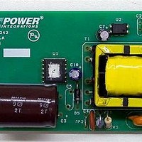
4 Circuit Description
This power supply employs a TOP266VG off-line switcher, (U1), in a flyback
configuration. IC U1 has an integrated 725 V MOSFET and a multi-mode controller. It
regulates the output by adjusting the MOSFET duty cycle, based on the current fed into
its CONTROL (C) pin.
4.1 Key Design Decisions
The goals of the design were highest full load efficiency, average efficiency (average of
25%, 50%, 75% and 100% load points) and very low no-load consumption.
Additional requirements included latching output overvoltage shutdown and compliance
to safety agency limited power source (LPS) limits. Actual efficiency and no-load
performance easily exceeded current energy efficiency requirements.
In order to meet these design goals the following key design decisions were made.
4.1.1 PI part selection
• Ambient of 40 °C allowed one device size smaller than indicated by the power table.
The device selected for this design was based on the 85-265 VAC, Open Frame, PCB
heatsinking column of the datasheet power table (Table 1). One device size smaller was
selected (TOP266V vs TOP267V) due to the ambient specification of 40 °C (vs. the 50°C
assumed in the power table) and the optimum PCB area and layout for the device
heatsink. The subsequent thermal and efficiency data confirmed this choice. The
maximum device temperature was 107 °C at full load, 40 °C, 85 VAC, 47 Hz (worst case
conditions) and average efficiency exceeded 83% ENERGY STAR and EuP Tier 2
requirements.
4.1.2 Transformer Core Selection
• 132 kHz switching frequency allowed the selection of smaller core for lower cost.
The size of the magnetic core is a function of the switching frequency. The choice of the
higher switching frequency of 132 kHz allowed for the use of a smaller core size. The
higher switching frequency does not negatively impact the efficiency in TOPSwitch-JX
designs due its small drain to source capacitance (C
MOSFETs.
4.1.3 Line Sense Resistor Values
• Increasing line sensing resistance from 4 MΩ to 10.2 MΩ to reduce no-load input power
dissipation by 16 mW
Line sensing is provided by resistors R1 and R2 and sets the line undervoltage and
overvoltage thresholds. The combined value of these resistors was increased from the
standard 4 M to 10.2 M. This reduced the resistor, and therefore contribution to no-
Power Integrations, Inc.
Tel: +1 408 414 9200 Fax: +1 408 414 9201
www.powerint.com
OSS
) as compared to that of discrete
Page 8 of 59
Related parts for RDK-242
Image
Part Number
Description
Manufacturer
Datasheet
Request
R

Part Number:
Description:
KIT REF DESIGN TOP HX FOR TOP258
Manufacturer:
Power Integrations
Datasheet:

Part Number:
Description:
KIT REF DESIGN LINKSWITCH 2
Manufacturer:
Power Integrations
Datasheet:

Part Number:
Description:
KIT REF DESIGN 1.2W PS TN FAMILY
Manufacturer:
Power Integrations
Datasheet:

Part Number:
Description:
KIT REF DESIGN 36-72W MOTOR DRVR
Manufacturer:
Power Integrations
Datasheet:

Part Number:
Description:
KIT REF DESIGN FOR LNK457D
Manufacturer:
Power Integrations
Datasheet:

Part Number:
Description:
REFERENCE DESIGN LINKSWITCH-PH
Manufacturer:
Power Integrations
Datasheet:

Part Number:
Description:
Specifications: Manufacturer: Power Integrations ; Output Voltage: 380 VDC ; Input / Supply Voltage (Max): 264 VAC ; Input / Supply Voltage (Min): 90 VAC ; Mounting Style: Through Hole ; Output Current: 0.913 A ; Output Power: 347 W
Manufacturer:
Power Integrations, Inc.
Part Number:
Description:
Power Management IC Development Tools REF DESIGN RDR-292 PFF LED STREET LIGHT
Manufacturer:
Power Integrations

Part Number:
Description:
KIT REF DESIGN FOR LNK403EG
Manufacturer:
Power Integrations
Datasheet:

Part Number:
Description:
KIT REF DESIGN FOR LNK406EG
Manufacturer:
Power Integrations
Datasheet:

Part Number:
Description:
KIT REF DESIGN DG CAPZERO
Manufacturer:
Power Integrations
Datasheet:

Part Number:
Description:
KIT REF DESIGN LINKSWITCH-CV
Manufacturer:
Power Integrations
Datasheet:

Part Number:
Description:
KIT REF DESIGN PFS762HG
Manufacturer:
Power Integrations
Datasheet:
Part Number:
Description:
Specifications: Family: Eval Boards - DC/DC & AC/DC (Off-Line) SMPS ; Series: HiperLCS™ ; Main Purpose: DC/DC, Step Down ; Outputs and Type: 1, Isolated ; Power - Output: 150W ; Voltage - Output: 24V ; Current - Output: 6.25A ; Voltage - Input:
Manufacturer:
Power Integrations, Inc.
Datasheet:

Part Number:
Description:
KIT REFERENCE DESIGN W/TN376PN
Manufacturer:
Power Integrations
Datasheet: