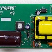
RDK-242 Power Integrations, RDK-242 Datasheet - Page 56

RDK-242
Manufacturer Part Number
RDK-242
Description
Power Management Modules & Development Tools TOPSwitch-JX REF. DESIGN KIT
Manufacturer
Power Integrations
Type
MOSFET & Power Driverr
Datasheet
1.RDK-242.pdf
(59 pages)
Specifications of RDK-242
Input Voltage
85 VAC to 264 VAC
Output Voltage
12 V
Maximum Operating Temperature
+ 40 C
Minimum Operating Temperature
0 C
Operating Supply Voltage
85 VAC to 264 VAC
Product
Power Management Modules
17 Appendix B: Circuit Modification for Reduced No-load Input Power
The TOPSwitch-JX family is designed to achieve very low no-load input power by
reducing the CONTROL pin current I
during MCM operation. The value of I
the primary control circuit which contributes to no-load input power losses. This primary
circuit loss can be optimized by properly selecting bias voltage to be low enough to
minimize the V
pin, typically V
condition at highest AC input/
Another circuit block to look for power savings is the secondary control circuit dissipation
during no-load. Power loss associated with the secondary control circuit is related to the
output voltage and the control current that flows in the optocoupler diode. The
optocoupler diode current is inversely proportional to the CTR of the optocoupler
(I
secondary side power consumption. In the circuit below, Q2 is added to form a Darlington
pair with the optocoupler transistor which now gives a very high equivalent CTR and thus
reduces the optocoupler current. This configuration will dramatically improve the no-load
power loss savings as shown in the data below. Note that this configuration will result in a
higher open loop gain and thus compensation circuit must be redesigned to maintain the
necessary stability margins (increasing the value of R19).
Figure 66 – Optocoupler Darlington Configuration to Reduce Feedback Current and No-load Input Power.
DOPTO
and Enhanced Output OVP Performance
~ I
Power Integrations, Inc.
Tel: +1 408 414 9200 Fax: +1 408 414 9201
www.powerint.com
C(OFF)
BIAS
BIAS(VALLEY)
/CTR), and therefore a higher CTR optocoupler will result in lower
x I
C(OFF)
~7 V. Note that the bias voltage is at minimum during no-load
product but high enough to maintain supply on the CONTROL
C(OFF)
C(OFF)
and the bias voltage dictates the power loss in
= 3.5 mA (typical for TOP266VG, 132 kHz)
Page 56 of 59


