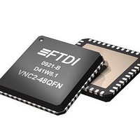
VNC2-48Q1B-REEL FTDI, VNC2-48Q1B-REEL Datasheet - Page 87

VNC2-48Q1B-REEL
Manufacturer Part Number
VNC2-48Q1B-REEL
Description
USB Interface IC Vinculum-II Dual USB Host/Dev IC QFN-48
Manufacturer
FTDI
Type
USB Host/Device Controllerr
Datasheet
1.VNC2-32Q1B-REEL.pdf
(90 pages)
Specifications of VNC2-48Q1B-REEL
Maximum Operating Temperature
+ 85 C
Minimum Operating Temperature
- 40 C
Mounting Style
SMD/SMT
Operating Temperature Range
- 40 C to + 85 C
Supply Current
25 mA
Operating Supply Voltage
1.8 V, 3.3V
Package / Case
QFN-48
Description/function
USB Vinculum-II Dual Host/Dev IC QFN-48
Lead Free Status / RoHS Status
Lead free / RoHS Compliant
Other names
VINCULUM2
Document No.: FT_000138
VINCULUM-II EMBEDDED DUAL USB HOST CONTROLLER IC Datasheet
1.2
Version -
143
Clearance No.: FTDI#
Appendix A – List of Figures and Tables
List of Tables
Table 1 Part Numbers .................................................................................................................... 3
Table 2 Acronyms and Abbreviations ............................................................................................... 4
Table 3 USB Interface Group ........................................................................................................ 18
Table 4 Power and Ground ........................................................................................................... 18
Table 5 Miscellaneous Signal Group ............................................................................................... 19
Table 6 Default I/O Configuration ................................................................................................. 22
Table 7 - Peripheral Pin Requirements ........................................................................................... 24
Table 8 I/O Peripherals Signal Names ........................................................................................... 31
Table 9 Group 0.......................................................................................................................... 33
Table 10 Group 1 ........................................................................................................................ 34
Table 11 Group 2 ........................................................................................................................ 35
Table 12 Group 3 ........................................................................................................................ 36
Table 13 Data and Control Bus Signal Mode Options – UART Interface ............................................... 40
Table 14 SPI Signal Names .......................................................................................................... 41
Table 15 - SPI Slave Speeds ........................................................................................................ 41
Table 16 - Clock Phase/Polarity Modes ........................................................................................... 42
Table 17 Data and Control Bus Signal Mode Options - SPI Slave Interface ........................................ 44
Table 18 SPI Command and Status Fields ...................................................................................... 45
Table 19 SPI Command and Status Fields ...................................................................................... 50
Table 20 SPI Setup Bit Encoding ................................................................................................... 51
Table 21 SPI Slave Data Timing .................................................................................................... 52
Table 22 SPI Master Data Read Status Bit ...................................................................................... 53
Table 23 SPI Master Data Write Status Bit ..................................................................................... 53
Table 24 SPI Status Read Byte – bit descriptions ............................................................................ 54
Table 25 SPI Master Signal Names ................................................................................................ 56
Table 26 SPI Master Timing ......................................................................................................... 57
Table 27 Debugger Signal Name .................................................................................................. 58
Table 28 Data and Control Bus Signal Mode Options - Parallel FIFO Interface ..................................... 61
Table 29 Asynchronous FIFO mode Read / Write Timing .................................................................. 63
Table 30 Synchronous FIFO control signals .................................................................................... 64
Table 31 Synchronous FIFO mode Read / Write Timing .................................................................... 66
Table 32 Absolute Maximum Ratings ............................................................................................. 72
Table 33 Operating Voltage and Current ........................................................................................ 73
Table 34 I/O Pin Characteristics .................................................................................................... 73
Table 37 ESD and Latch-up Specifications ...................................................................................... 75
Table 38 Reflow Profile Parameter Values ...................................................................................... 85
Table 39 Package Reflow Peak Temperature ................................................................................... 85
Copyright © 2010 Future Technology Devices International Limited
87


