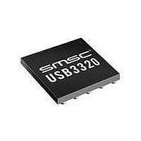
USB3300-EZK-TR SMSC, USB3300-EZK-TR Datasheet - Page 21

USB3300-EZK-TR
Manufacturer Part Number
USB3300-EZK-TR
Description
USB Interface IC USB 2.0 PHY ULPI
Manufacturer
SMSC
Type
Hi Speed USB Host Devicer
Datasheet
1.USB3300-EZK.pdf
(55 pages)
Specifications of USB3300-EZK-TR
Maximum Operating Temperature
+ 85 C
Minimum Operating Temperature
- 40 C
Mounting Style
SMD/SMT
Operating Temperature Range
- 40 C to + 85 C
Operating Supply Voltage
3.3 V
Package / Case
QFN-32
Lead Free Status / RoHS Status
Lead free / RoHS Compliant
Available stocks
Company
Part Number
Manufacturer
Quantity
Price
Company:
Part Number:
USB3300-EZK-TR
Manufacturer:
MICRON
Quantity:
3 140
Part Number:
USB3300-EZK-TR
Manufacturer:
MICROCHIP/微芯
Quantity:
20 000
Hi-Speed USB Host, Device or OTG PHY with ULPI Low Pin Interface
Datasheet
SMSC USB3300
6.1.2
DATA[7:0]
CLKOUT
SIGNAL
STP
NXT
DIR
In Figure 6.2, "ULPI Digital Block Diagram", a single ULPI Protocol Block decodes the ULPI 8-bit bi-
directional bus when the Link addresses the PHY. The Link must use the DIR output to determine
direction of the ULPI data bus. The USB3300 is the “bus arbitrator”. The ULPI Protocol Block will route
data/commands to the transmitter or the ULPI register array.
ULPI Interface Signals
UTMI+ Low Pin Interface (ULPI) uses 12-pins to connect a full OTG Host / Device PHY to an SOC.
A reduction of external pins on the PHY is accomplished by realizing that many of the relatively static
configuration pins (xcvrselect[1:0], termselect, opmode[1:0], and DpPullDown DmPulldown to list a
few,) can be implemented by having a internal static register array.
An 8-bit bi-directional data bus clocked at 60Mhz allows the Link to access this internal register array
and transfer USB packets to and from the PHY. The remaining 3 pins function to control the data flow
and arbitrate the data bus.
Direction of the 8-bit data bus is control by the DIR output from the PHY. Another output NXT is used
to control data flow into and out of the device. Finally, STP, which is in input to the PHY, terminates
transfers and is used to start up and resume from a suspend state.
The 12 signals are described below in
USB3300 implements a Single Data Rate (SDR) ULPI interface with all data transfers happening on
the rising edge of the CLKOUT. CLKOUT is supplied by the PHY.
The ULPI interface supports the two basic modes of operation, Synchronous Mode and Low Power
Mode. Synchronous Mode with the signals all changing relative to the 60MHz clockout. Low Power
Mode where the clock is off in a suspended state and the lower two bits of the data bus contain the
linestate[1:0] signals. ULPI adds to Low Power Mode, an interrupt output which permits the Link to
receive an asynchronous interrupt when the OTG comparators, or ID pin change state.
In Synchronous Mode operation, data is transferred on the rising edge of CLKOUT. Direction of the
data bus is determined by the state of DIR. When DIR is high, the PHY is driving DATA[7:0]. When
DIR is low, the Link is driving DATA[7:0].
DIRECTION
OUT
OUT
OUT
I/O
IN
60MHz reference clock output. All ULPI signals are driven synchronous to the
rising edge of this clock.
8-bit bi-directional data bus. Bus ownership is determined by DIR. The Link and
PHY initiate data transfers by driving a non-zero pattern onto the data bus. ULPI
defines interface timing for a single-edge data transfers with respect to rising edge
of CLKOUT.
Controls the direction of the data bus. When the PHY has data to transfer to the
Link, it drives DIR high to take ownership of the bus. When the PHY has no data
to transfer it drives DIR low and monitors the bus for commands from the Link. The
PHY will pull DIR high whenever the interface cannot accept data from the Link,
such as during PLL start-up.
The Link asserts STP for one clock cycle to stop the data stream currently on the
bus. If the Link is sending data to the PHY, STP indicates the last byte of data was
on the bus in the previous cycle.
The PHY asserts NXT to throttle the data. When the Link is sending data to the
PHY, NXT indicates when the current byte has been accepted by the PHY. The
Link places the next byte on the data bus in the following clock cycle.
Table 6.1 ULPI Interface Signals
DATASHEET
Table 6.1, "ULPI Interface
21
DESCRIPTION
Signals".
Revision 1.08 (11-07-07)


