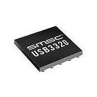
USB3300-EZK-TR SMSC, USB3300-EZK-TR Datasheet - Page 46

USB3300-EZK-TR
Manufacturer Part Number
USB3300-EZK-TR
Description
USB Interface IC USB 2.0 PHY ULPI
Manufacturer
SMSC
Type
Hi Speed USB Host Devicer
Datasheet
1.USB3300-EZK.pdf
(55 pages)
Specifications of USB3300-EZK-TR
Maximum Operating Temperature
+ 85 C
Minimum Operating Temperature
- 40 C
Mounting Style
SMD/SMT
Operating Temperature Range
- 40 C to + 85 C
Operating Supply Voltage
3.3 V
Package / Case
QFN-32
Lead Free Status / RoHS Status
Lead free / RoHS Compliant
Available stocks
Company
Part Number
Manufacturer
Quantity
Price
Company:
Part Number:
USB3300-EZK-TR
Manufacturer:
MICRON
Quantity:
3 140
Part Number:
USB3300-EZK-TR
Manufacturer:
MICROCHIP/微芯
Quantity:
20 000
Chapter 7 Application Notes
Revision 1.08 (11-07-07)
C
C
C
C
R
ID Pin
DESIGNATOR
REFERENCE
OUT
VBUS
BYP
DC_BLOCK
VBUS
The USB3300 requires few external components as shown in the application diagrams. In some
applications, the power supplied on the VBUS and GND pins of the USB connector is used as the
source of system power. The USB2.0 standard restricts the voltage at the VBUS pin to a maximum
value of 5.25V. In some applications, it may be required to provide protection to the USB3300 VBUS
pin if the VBUS voltage exceeds the USB2.0 specifications.
One method of protecting the VBUS pin from excessive voltage (transients) is to place a resistor
(R
"USB3300 Application Diagram (Host or OTG)". The resistor provides protection against transients that
exceed the value of V
is installed, the transient must not be allowed to exceed the value of V
To protect the VBUS pin against a steady state voltage on the USB connector that exceeds the value
of V
in Figure 7.3, "USB3300 Application Diagram (Peripheral with Over Voltage Protection)".
In addition to the capacitors shown in the application diagrams, each VDD pin should have an
additional capacitor to ground, of value 0.01 or 0.1 μF (not shown for clarity). Approximately equal
numbers of each value should be used.
VBUS
VBUS
4.7μF
See
"Capacitance
Values at VBUS
of USB
Connector"
System
dependent.
System
dependent.
Max of 820Ω in
Host or OTG
applications.
) in series as shown in Figure 7.1, "USB3300 Application Diagram (Peripheral)" and Figure 7.2,
provided in
Table 7.2,
VALUE
Table 7.2 Capacitance Values at VBUS of USB Connector
Table 7.1 Component Values in Application Diagrams
VBUS
Table
Host
Device
OTG
MODE
Bypass capacitors to ground (<1Ω
ESR) for regulator stability.
Capacitor to ground required by the
USB Specification. SMSC
recommends <1Ω ESR.
Bypass capacitor to ground.
The USB connector housing may be
AC-coupled to the device ground.
Series resistor to reduce any transient
voltage on the VBUS pin of the
USB3300.
provided in
4.2, an Over Voltage Protection (OVP) component can be used as shown
MIN VALUE
120μF
1μF
1μF
DATASHEET
DESCRIPTION
Table 4.2, "Recommended Operating
Hi-Speed USB Host, Device or OTG PHY with ULPI Low Pin Interface
46
10μF
6.5μF
MAX VALUE
NOTES
Place as close as possible to the
PHY.
Place near the USB connector.
Place as close as possible to the
PHY.
Industry convention is to ground
only the host side of the cable
shield.
The transient must not be
allowed to exceed the value of
V
Okay to leave No Connection
(NC) in device mode.
VBUS
VBUS
for longer than 500 μs
Conditions". When R
for longer than 500 μs.
SMSC USB3300
Datasheet
VBUS


