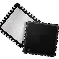
ispPAC-POWR607-01SN32I Lattice, ispPAC-POWR607-01SN32I Datasheet - Page 13

ispPAC-POWR607-01SN32I
Manufacturer Part Number
ispPAC-POWR607-01SN32I
Description
Supervisory Circuits Prec Prog Pwr Supply Seq Mon IND
Manufacturer
Lattice
Type
Power Supply Sequencer and Monitorr
Series
ispPAC®r
Datasheet
1.ISPPAC-POWR607-01SN32I.pdf
(28 pages)
Specifications of ispPAC-POWR607-01SN32I
Internal Hysteresis
Yes
Minimum Operating Temperature
- 40 C
Output Type
Open Collector / Drain
Power Fail Detection
Yes
Number Of Voltages Monitored
6
Monitored Voltage
Adj V
Undervoltage Threshold
Adj
Overvoltage Threshold
Adj
Manual Reset
Resettable
Watchdog
Yes
Power-up Reset Delay (typ)
100 us
Supply Voltage (max)
3.96 V
Supply Voltage (min)
2.64 V
Supply Current (typ)
3.5 mA
Mounting Style
SMD/SMT
Maximum Operating Temperature
+ 85 C
Package / Case
QFN-32
Applications
General Purpose
Voltage - Input
-0.3 V ~ 5.9 V
Voltage - Supply
2.64 V ~ 3.96 V
Current - Supply
3.5mA
Operating Temperature
-40°C ~ 85°C
Mounting Type
Surface Mount
Lead Free Status / RoHS Status
Lead free / RoHS Compliant
Available stocks
Company
Part Number
Manufacturer
Quantity
Price
Company:
Part Number:
ISPPAC-POWR607-01SN32I
Manufacturer:
LATTICE
Quantity:
284
Part Number:
ISPPAC-POWR607-01SN32I
Manufacturer:
LATTICE
Quantity:
20 000
Lattice Semiconductor
Table 4-3. Comparator Hysteresis vs. Trip-Point
The second section in the ispPAC-POWR607’s input voltage monitor is a digital filter. When enabled, the compara-
tor output will be delayed by a filter time constant of 48µS, and is especially useful for reducing the possibility of
false triggering from noise that may be present on the voltages being monitored. When the filter is disabled, the
comparator output will be delayed by 12µS. In both cases, enabled or disabled, the filters also provide synchroniza-
tion of the input signals to the PLD clock. This synchronous sampling feature effectively eliminates the possibility of
race conditions from occurring in any subsequent logic that is implemented in the ispPAC-POWR607’s internal PLD
logic.
PLD Block
Figure 4-10 shows the ispPAC-POWR607 PLD architecture, which is derived from Lattice's ispMACH™ 4000
CPLD. The PLD architecture allows flexibility in designing various state machines and control functions for power
supply management. The AND array has 28 inputs and generates 81 product terms. The product terms are fed into
a single logic block made up of 16 macrocells. The output signals of the ispPAC-POWR607 device are derived from
the PLD as shown in Figure 4-10.
Low Limit
0.667
0.796
0.947
1.126
1.336
1.594
1.897
2.254
2.671
3.181
4.082
4.861
Trip-point Range (V)
75 mV
High Limit
0.798
0.950
1.131
1.347
1.596
1.904
2.268
2.693
3.192
3.803
4.878
5.811
4-13
Hysteresis (mV)
0 (Disabled)
10
12
14
17
19
23
28
33
39
50
60
8
ispPAC-POWR607 Data Sheet


