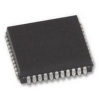
AT80C51RD2-SLSUM Atmel, AT80C51RD2-SLSUM Datasheet - Page 53

AT80C51RD2-SLSUM
Manufacturer Part Number
AT80C51RD2-SLSUM
Description
MCU, 8BIT, 8051, 5V, SPI, 20MHZ, 44PLCC
Manufacturer
Atmel
Specifications of AT80C51RD2-SLSUM
Controller Family/series
(8051) 8052
No. Of I/o's
32
Ram Memory Size
1280Byte
Cpu Speed
40MHz
No. Of Timers
3
No. Of Pwm Channels
5
Core Size
8bit
Oscillator Type
External Only
Processor Series
AT80x
Core
8051
Data Bus Width
8 bit
Program Memory Type
ROMLess
Data Ram Size
1280 B
Interface Type
UART, SPI
Maximum Clock Frequency
60 MHz
Number Of Programmable I/os
32
Number Of Timers
3
Operating Supply Voltage
2.7 V to 5.5 V
Maximum Operating Temperature
+ 85 C
Mounting Style
SMD/SMT
Package / Case
PLCC
3rd Party Development Tools
PK51, CA51, A51, ULINK2
Minimum Operating Temperature
- 40 C
Cpu Family
AT80
Device Core
8051
Device Core Size
8b
Frequency (max)
40MHz
Program Memory Size
Not Required
Total Internal Ram Size
1.25KB
# I/os (max)
32
Number Of Timers - General Purpose
3
Operating Supply Voltage (typ)
3.3/5V
Operating Supply Voltage (max)
5.5V
Operating Supply Voltage (min)
2.7V
Instruction Set Architecture
CISC
Operating Temp Range
-40C to 85C
Operating Temperature Classification
Industrial
Mounting
Surface Mount
Pin Count
44
Package Type
PLCC
Lead Free Status / RoHS Status
Lead free / RoHS Compliant
Lead Free Status / RoHS Status
Lead free / RoHS Compliant
Available stocks
Company
Part Number
Manufacturer
Quantity
Price
Company:
Part Number:
AT80C51RD2-SLSUM
Manufacturer:
Atmel
Quantity:
1 445
9. TS87C51RB2/RC2/RD2 EPROM
9.1
9.2
9.2.1
9.2.2
4188F–8051–01/08
EPROM Structure
EPROM Lock System
Encryption Array
Program Lock Bits
The TS87C51RB2/RC2/RD2 EPROM is divided in two different arrays:
In addition a third non programmable array is implemented:
The program Lock system, when programmed, protects the on-chip program against software
piracy.
Within the EPROM array are 64 bytes of encryption array that are initially unprogrammed (all
FF’s). Every time a byte is addressed during program verify, 6 address lines are used to select a
byte of the encryption array. This byte is then exclusive-NOR’ed (XNOR) with the code byte, cre-
ating an encrypted verify byte. The algorithm, with the encryption array in the unprogrammed
state, will return the code in its original, unmodified form.
When using the encryption array, one important factor needs to be considered. If a byte has the
value FFh, verifying the byte will produce the encryption byte value. If a large block (>64 bytes)
of code is left unprogrammed, a verification routine will display the content of the encryption
array. For this reason all the unused code bytes should be programmed with random values.
This will ensure program protection.
The three lock bits, when programmed according to Table 9-1.9.2.3, will provide different level of
protection for the on-chip code and data.
Table 9-1.
U: unprogrammed,
P: programmed
• the code array:16/32/64 Kbytes.
• the encryption array:64 bytes.
• the signature array: 4 bytes.
Security
level
1
2
3
4
Program Lock bits
Program Lock Bits
LB1
U
P
U
U
LB2
U
U
P
U
LB3
U
U
U
P
Protection Description
No program lock features enabled. Code verify will still be
encrypted by the encryption array if programmed. MOVC
instruction executed from external program memory returns non
encrypted data.
MOVC instruction executed from external program memory are
disabled from fetching code bytes from internal memory, EA is
sampled and latched on reset, and further programming of the
EPROM is disabled.
Same as 2, also verify is disabled.
Same as 3, also external execution is disabled.
AT/TS8xC51Rx2
53


