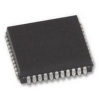
AT80C51RD2-SLSUM Atmel, AT80C51RD2-SLSUM Datasheet - Page 56

AT80C51RD2-SLSUM
Manufacturer Part Number
AT80C51RD2-SLSUM
Description
MCU, 8BIT, 8051, 5V, SPI, 20MHZ, 44PLCC
Manufacturer
Atmel
Specifications of AT80C51RD2-SLSUM
Controller Family/series
(8051) 8052
No. Of I/o's
32
Ram Memory Size
1280Byte
Cpu Speed
40MHz
No. Of Timers
3
No. Of Pwm Channels
5
Core Size
8bit
Oscillator Type
External Only
Processor Series
AT80x
Core
8051
Data Bus Width
8 bit
Program Memory Type
ROMLess
Data Ram Size
1280 B
Interface Type
UART, SPI
Maximum Clock Frequency
60 MHz
Number Of Programmable I/os
32
Number Of Timers
3
Operating Supply Voltage
2.7 V to 5.5 V
Maximum Operating Temperature
+ 85 C
Mounting Style
SMD/SMT
Package / Case
PLCC
3rd Party Development Tools
PK51, CA51, A51, ULINK2
Minimum Operating Temperature
- 40 C
Cpu Family
AT80
Device Core
8051
Device Core Size
8b
Frequency (max)
40MHz
Program Memory Size
Not Required
Total Internal Ram Size
1.25KB
# I/os (max)
32
Number Of Timers - General Purpose
3
Operating Supply Voltage (typ)
3.3/5V
Operating Supply Voltage (max)
5.5V
Operating Supply Voltage (min)
2.7V
Instruction Set Architecture
CISC
Operating Temp Range
-40C to 85C
Operating Temperature Classification
Industrial
Mounting
Surface Mount
Pin Count
44
Package Type
PLCC
Lead Free Status / RoHS Status
Lead free / RoHS Compliant
Lead Free Status / RoHS Status
Lead free / RoHS Compliant
Available stocks
Company
Part Number
Manufacturer
Quantity
Price
Company:
Part Number:
AT80C51RD2-SLSUM
Manufacturer:
Atmel
Quantity:
1 445
Figure 9-2.
9.4
9.4.1
10. Signature Bytes
56
EPROM Erasure (Windowed Packages Only)
AT/TS8xC51Rx2
Erasure Characteristics
Control signals
Programming and Verification Signal’s Waveform
ALE/PROG
A0-A12
EA/VPP
D0-D7
The encryption array cannot be directly verified. Verification of the encryption array is done by
observing that the code array is well encrypted.
Erasing the EPROM erases the code array, the encryption array and the lock bits returning the
parts to full functionality.
Erasure leaves all the EPROM cells in a 1’s state (FF).
The recommended erasure procedure is exposure to ultraviolet light (at 2537 Å) to an integrated
dose at least 15 W-sec/cm
ing for 30 minutes, at a distance of about 25 mm, should be sufficient. An exposure of 1 hour is
recommended with most of standard erasers.
Erasure of the EPROM begins to occur when the chip is exposed to light with wavelength
shorter than approximately 4,000 Å. Since sunlight and fluorescent lighting have wavelengths in
this range, exposure to these light sources over an extended time (about 1 week in sunlight, or 3
years in room-level fluorescent lighting) could cause inadvertent erasure. If an application sub-
jects the device to this type of exposure, it is suggested that an opaque label be placed over the
window.
The
read these bytes follow the procedure for EPROM verify but activate the control lines provided in
Table 31. for Read Signature Bytes. Table 10-1. shows the content of the signature byte for the
TS87C51RB2/RC2/RD2.
Table 10-1.
12.75V
5V
0V
TS83/87C51RB2/RC2/RD2
Programming Cycle
Signature Bytes Content
Location
Data In
30h
31h
60h
100µs
2
. Exposing the EPROM to an ultraviolet lamp of 12,000 µW/cm
has four signature bytes in location 30h, 31h, 60h and 61h. To
Contents
7Ch
58h
57h
Read/Verify Cycle
Data Out
Comment
Manufacturer Code: Atmel
Family Code: C51 X2
Product name: TS83C51RD2
4188F–8051–01/08
2
rat-


