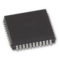
AT80C51RD2-SLSUM Atmel, AT80C51RD2-SLSUM Datasheet - Page 63

AT80C51RD2-SLSUM
Manufacturer Part Number
AT80C51RD2-SLSUM
Description
MCU, 8BIT, 8051, 5V, SPI, 20MHZ, 44PLCC
Manufacturer
Atmel
Specifications of AT80C51RD2-SLSUM
Controller Family/series
(8051) 8052
No. Of I/o's
32
Ram Memory Size
1280Byte
Cpu Speed
40MHz
No. Of Timers
3
No. Of Pwm Channels
5
Core Size
8bit
Oscillator Type
External Only
Processor Series
AT80x
Core
8051
Data Bus Width
8 bit
Program Memory Type
ROMLess
Data Ram Size
1280 B
Interface Type
UART, SPI
Maximum Clock Frequency
60 MHz
Number Of Programmable I/os
32
Number Of Timers
3
Operating Supply Voltage
2.7 V to 5.5 V
Maximum Operating Temperature
+ 85 C
Mounting Style
SMD/SMT
Package / Case
PLCC
3rd Party Development Tools
PK51, CA51, A51, ULINK2
Minimum Operating Temperature
- 40 C
Cpu Family
AT80
Device Core
8051
Device Core Size
8b
Frequency (max)
40MHz
Program Memory Size
Not Required
Total Internal Ram Size
1.25KB
# I/os (max)
32
Number Of Timers - General Purpose
3
Operating Supply Voltage (typ)
3.3/5V
Operating Supply Voltage (max)
5.5V
Operating Supply Voltage (min)
2.7V
Instruction Set Architecture
CISC
Operating Temp Range
-40C to 85C
Operating Temperature Classification
Industrial
Mounting
Surface Mount
Pin Count
44
Package Type
PLCC
Lead Free Status / RoHS Status
Lead free / RoHS Compliant
Lead Free Status / RoHS Status
Lead free / RoHS Compliant
Available stocks
Company
Part Number
Manufacturer
Quantity
Price
Company:
Part Number:
AT80C51RD2-SLSUM
Manufacturer:
Atmel
Quantity:
1 445
4188F–8051–01/08
T
T
Table 11-3. gives the maximum applicable load capacitance for Port 0, Port 1, 2 and 3, and ALE
and PSEN signals. Timings will be guaranteed if these capacitances are respected. Higher
capacitance values can be used, but timings will then be degraded.
Table 11-3.
Table 11-5., Table 39. and Table 42. give the description of each AC symbols.
Table 11-6., Table 11-8. and Table 11-10. give for each range the AC parameter.
Table 11-7., Table 11-9. and Table 11-11. give the frequency derating formula of the AC param-
eter. To calculate each AC symbols, take the x value corresponding to the speed grade you
need (-M, -V or -L) and replace this value in the formula. Values of the frequency must be limited
to the corresponding speed grade:
Table 11-4.
Example:
T
A
A
LLIV
ALE / PSEN
Freq (MHz)
Port 1, 2, 3
= 0 to +70°C (commercial temperature range); V
= -40°C to +85°C (industrial temperature range); V
T (ns)
Port 0
in X2 mode for a -V part at 20 MHz (T = 1/20
x= 22 (Table 11-7.)
T= 50ns
T
Load Capacitance versus speed range, in pF
Max frequency for derating formula regarding the speed grade
LLIV
-M X1 mode
= 2T - x = 2 x 50 - 22 = 78ns
40
25
100
100
-M
80
-M X2 mode
20
50
-V X1 mode
40
25
E6
SS
= 50 ns):
SS
= 0 V; 2.7 V < V
-V
50
50
30
= 0 V; 2.7 V < V
-V X2 mode
33.3
30
AT/TS8xC51Rx2
CC <
-L X1 mode
CC <
33.3
30
5.5 V; -L range.
5.5 V; -L range.
100
100
80
-L
-L X2 mode
20
50
63


