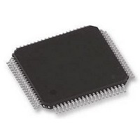
UPD78F1154GK-GAK-AX NEC, UPD78F1154GK-GAK-AX Datasheet - Page 38

UPD78F1154GK-GAK-AX
Manufacturer Part Number
UPD78F1154GK-GAK-AX
Description
16BIT MCU, 128K FLASH, 8K RAM, SMD
Manufacturer
NEC
Datasheet
1.UPD78F1154GK-GAK-AX.pdf
(84 pages)
Specifications of UPD78F1154GK-GAK-AX
Controller Family/series
UPD78F
No. Of I/o's
70
Ram Memory Size
8192Byte
Cpu Speed
20MHz
No. Of Timers
9
No. Of
RoHS Compliant
Core Size
16bit
Program Memory Size
128KB
Oscillator Type
External, Internal
Available stocks
Company
Part Number
Manufacturer
Quantity
Price
Company:
Part Number:
UPD78F1154GK-GAK-AX
Manufacturer:
NEC
Quantity:
100
38
The timer array unit consists of the following registers.
<Registers of unit setting block>
(1) Peripheral enable register 0 (PER0)
(2) Timer clock select register 0 (TPS0)
(3) Timer channel enable status register 0 (TE0)
(4) Timer channel start register 0 (TS0)
(5) Timer channel stop register 0 (TT0)
(6) Timer input select register 0 (TIS0)
(7) Noise filter enable register 1 (NFEN1)
(8) Timer output enable register 0 (TOE0)
(9) Timer output register 0 (TO0)
(10) Timer output level register 0 (TOL0)
(11) Timer output mode register 0 (TOM0)
Bit 0 of this register enables or stops operation of the timer array unit. The default value of this bit is set to
stop the operation of the timer array unit.
This register is used to set a division ratio of the CK00 and CK01 clocks when they are generated, by dividing
the peripheral hardware clock. The CK00 and CK01 clocks are commonly supplied to channels 0 to 7 of each
unit.
This register is used to enable or stop the timer operation of each channel.
This is a trigger register that is used to clear a timer counter (TCR0n) and start the counting operation of each
channel.
This is a trigger register that stops the counting operation of each channel.
This register is used to select the input signal of a timer input pin (TI0n) or subsystem clock divided by 4 (f
for each channel.
This register is used to set whether the noise filter can be used for the timer input signal to each channel.
This register is used to enable or stop the timer output of each channel.
This is a buffer register of timer output. The value of each bit in this register is output from the timer output pin
(TO0n) of each channel.
TOL0 is a register that controls the timer output level of each channel.
The setting of the inverted output of channel n by this register is reflected at the timing of set or reset of the
timer output signal while the timer output is enabled (TOE0n = 1) in the combination operation mode (TOM0n
= 1).
This register is used to set an output mode of timer output (toggle operation or combination operation) for each
channel.
Preliminary Product Information U17892EJ2V0PM
78K0R/KF3
XT
/4)


