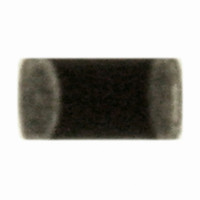
ERT-J0ER104J Panasonic - ECG, ERT-J0ER104J Datasheet - Page 10

ERT-J0ER104J
Manufacturer Part Number
ERT-J0ER104J
Description
THERMISTOR NTC 100K OHM 5% 0402
Manufacturer
Panasonic - ECG
Series
ERT-Jr
Datasheet
1.ERT-J0ER104J.pdf
(18 pages)
Specifications of ERT-J0ER104J
Resistance In Ohms @ 25°c
100K
Resistance Tolerance
±5%
B Value Tolerance
±2%
B25/50
4250K
B25/85
4300K
Operating Temperature
-40°C ~ 125°C
Power - Max
66mW
Mounting Type
Surface Mount
Package / Case
0402 (1005 Metric)
Lead Free Status / RoHS Status
Lead free / RoHS Compliant
B0/50
-
B25/75
-
B25/100
-
Lead Length
-
Other names
ERTJ0ER104J
P13703TR
P13703TR
CLASSIFICATION
SUBJECT
3.
3- 1.Storage
3- 2.Chip Mounting Consideration
Note ;
2-2-4. Component Layout
2-2-5. Mounting Density and Spaces
Precautions for Assembly
(1) The Thermistors before mounting on PCB shall be stored between 5 - 40°C and 20 - 70% RH, not under severe
(2) If stored in a place that is humid, dusty, or contains corrosive gasses (hydrogen sulfide, sulfurous acid,
(3) Do not store components longer than 6 months. Check the solderability of products that have been stored for
(1) When mounting the Thermistors/components on a PC board, the Thermistor bodies shall be free from excessive
(2) Maintenance and inspection of the Chip Mounter must be performed regularly.
(3) If the bottom dead center of the vacuum nozzle is too low, the Thermistor will be cracked by excessive force
Warp of
Circuit board
conditions of high temperature and humidity.
hydrogen chloride and ammonia, etc.), the solderability of terminal electrodes may deteriorate.
In addition, storage in a place subjected to heating and/or exposed to direct sunlight will cause deformed tapes
and reels. This may also lead to components sticking to tapes. Both of which can result in mounting problems.
more than 6 months before use.
impact loads such as mechanical impact or stress due to the positioning, pushing force and displacement of
vacuum nozzles during mounting.
during mounting.
The following precautions and recommendations are for your reference in use.
(a) Set and adjust the bottom dead center of the vacuum nozzles to the upper surface of the PC board after
(b) Set the pushing force of the vacuum nozzle during mounting to 1 to 3 N in static load.
(c) For double surface mounting, apply a supporting pin on the rear surface of the PC board to suppress the
The Thermistors/components shall be placed on the PC board such that both electrodes are subjected to
uniform stresses, or to position the component electrodes at right angles to the grid glove or bending line. This
should be done to avoid cracking the Thermistors from bending the PC board after or during placing/mounting
on the PC board.
If components are arranged in too narrow a space,
the components can be affected by solder bridges
and solder balls. The space between components
should be carefully determined.
(1) To minimize mechanical stress caused by warp or bending of a PC board, please follow the recommended
(2) The following layout is for your reference since
(3) The magnitude of mechanical stress applied to
correcting the warp of the PC board.
bending of the PC board in order to minimize the impact of the vacuum nozzles. Typical examples are
shown in the following table.
Thermistor layout below.
mechanical stress near the dividing/breaking
position of a PC board varies depending on the
mounting position of the Thermistors.
the Thermistors when the circuit board is divided
is in the order of push back < slit < V-groove <
perforation.
Also take into account the layout of the
Thermistors and the dividing/breaking method.
Common Specification (Precautions for Use)
Multilayer Chip NTC Thermistors
NG layout
SPECIFICATIONS
Perforation
Recommended layout
Magnitude of stress A>B=C>D>
A
E
Lay out the Thermistor
Slit
sideways against the
C
stressing direction
No.
PAGE
DATE
151S-ERTJ-SS03E
D
May 12, 2006
B
3 of 7


