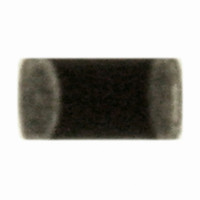
ERT-J0ER104J Panasonic - ECG, ERT-J0ER104J Datasheet - Page 6

ERT-J0ER104J
Manufacturer Part Number
ERT-J0ER104J
Description
THERMISTOR NTC 100K OHM 5% 0402
Manufacturer
Panasonic - ECG
Series
ERT-Jr
Datasheet
1.ERT-J0ER104J.pdf
(18 pages)
Specifications of ERT-J0ER104J
Resistance In Ohms @ 25°c
100K
Resistance Tolerance
±5%
B Value Tolerance
±2%
B25/50
4250K
B25/85
4300K
Operating Temperature
-40°C ~ 125°C
Power - Max
66mW
Mounting Type
Surface Mount
Package / Case
0402 (1005 Metric)
Lead Free Status / RoHS Status
Lead free / RoHS Compliant
B0/50
-
B25/75
-
B25/100
-
Lead Length
-
Other names
ERTJ0ER104J
P13703TR
P13703TR
CLASSIFICATION
SUBJECT
Note ;
No.
10 Moisture Resistance
11 Damp Heat Load
7 Resistance to
8 Solderability
9 Temperature Cycling
soldering heat
Test
Common Specification for Standard Type
Multilayer Chip NTC Thermistors
There shall be no cracks and other mechanical
damage.
Change of Zero-power Resistance (R
Change of B Value :
More than 75% of the soldered area of both
terminal electrodes shall be covered with fresh
solder.
Change of Zero-power Resistance (R
Change of B Value :
Change of Zero-power Resistance (R
Change of B Value :
Change of Zero-power Resistance (R
Change of B Value :
Within +/-3%
Within +/-2%
Within +/-3%
Within +/-2%
Within +/-3%
Within +/-2%
Within +/-3%
Within +/-2%
SPECIFICATIONS
Performance
(
to be continued
Table 2
25
25
25
25
) :
) :
) :
) :
)
Solder temperature : 270 +/-5 deg.C
Dipping period
Specimens shall be dipped in solder so that both ter-
minal electrodes are completely immersed.
Preconditioning : Heat treatment
Solder : H63A(JIS-Z-3282)
Flux: Concentration about 25% by weight of Rosin
Solder temperature : 230 +/-5 deg.C
Dipping period
A specimen shall be dipped so that both terminal elec-
trodes are completely immersed.
Solder : H63A(JIS-Z-3282)
Flux: Concentration about 25% by weight of Rosin
Dipping holder
Specimens shall be soldered on the testing jig shown
in Fig. 2.
The specimens are conditioned to be each tempera-
ture from step 1 to 4 in this order for the period shown
in the table below.
Regarding this conditioning as one cycle,
100 cycles shall be continuously performed.
Specimens shall be soldered on the testing board
shown in Fig.2.
Test temperature
Relative humidity : 85 +/-5 %
Test period
Specimens shall be soldered on the testing board
shown in Fig.2.
Test temperature
Relative humidity : 85 +/-5 %
Applied power
Test period
Step
1
2
3
4
(JIS-K-5902) ethanol solution
(JIS-K-5902) ethanol solution
Step
1
2
Room temperature
Room temperature
Temperature(°C)
150 to 200
80 to 100
125 +/- 5
(deg.C)
-40 +/- 3
Temp.
: 3.0 +/-0.5 s
: 4 +/- 1 s
: 85 +/-2 deg.C
: 1000 +48/-0 h
: 85 +/-2 deg.C
: 10 mW (D.C.)
: 1000 +48/-0 h
: Tweezers
Test Method
No.
PAGE
DATE
151S-ERTJ-SG07E
120 to 180
120 to 180
Period
(s)
Period(min)
May 12, 2006
30 +/- 3
30 +/- 3
3 max.
3 max.
4 of 5


