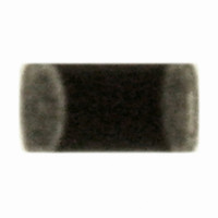
ERT-J0ER104J Panasonic - ECG, ERT-J0ER104J Datasheet - Page 14

ERT-J0ER104J
Manufacturer Part Number
ERT-J0ER104J
Description
THERMISTOR NTC 100K OHM 5% 0402
Manufacturer
Panasonic - ECG
Series
ERT-Jr
Datasheet
1.ERT-J0ER104J.pdf
(18 pages)
Specifications of ERT-J0ER104J
Resistance In Ohms @ 25°c
100K
Resistance Tolerance
±5%
B Value Tolerance
±2%
B25/50
4250K
B25/85
4300K
Operating Temperature
-40°C ~ 125°C
Power - Max
66mW
Mounting Type
Surface Mount
Package / Case
0402 (1005 Metric)
Lead Free Status / RoHS Status
Lead free / RoHS Compliant
B0/50
-
B25/75
-
B25/100
-
Lead Length
-
Other names
ERTJ0ER104J
P13703TR
P13703TR
CLASSIFICATION
SUBJECT
4.
3- 7.Protective Coating
3- 8.Dividing/Breaking of PC Boards
3- 9.Mechanical Impact
Note ;
Other
The various precautions described above are typical.
For special mounting conditions, please contact us.
PC board
When the surface of a PC board on which the Thermistors have been mounted is coated with resin to protect
against moisture and dust, it shall be confirmed that the protective coating does not influence the reliability of the
Thermistors in the actual equipment.
(1) Do not use coating materials that are corrosive or chemically active.
(2) Do not use coating materials with large thermal expansivity to prevent damage to the Thermistors during the
(1) Abnormal and excessive mechanical stress such as bending or torsion
(2) Dividing/Breaking of the PC boards shall be done carefully at moderate
(3) Examples of PCB dividing/breaking jigs:
(1) The Thermistors shall be free from any excessive mechanical impact.
(2) When handling PC boards with Thermistors mounted on them, do not allow
curing process.
shown below can cause cracking in the Thermistors.
speed by using a jig or apparatus to prevent the Thermistors on the boards
from mechanical damage.
The outline of PC board breaking jig is shown below.
It is recommended when dividing or breaking PC boards that they are held near the jig where no bending will
occur, this way there will be no compressive stress applied to the components or Thermistors on the PC board.
Do not hold the PC board at a position which is far away from the jig, tensile stress to the Thermistors may
cause them to crack.
The Thermistor body is made of ceramics and may be damaged or cracked
if dropped.
Never use a Thermistor which has been dropped; their quality may be
impaired and failure rate increased.
the Thermistors to collide with another PC board.
When mounted PC boards are handled or stored in a stacked state, impact
between the corner of a PC board and the Thermistor may cause damage
or cracking and can deteriorate the withstand voltage and insulation
resistance of the Thermistor.
Outline of Jig
Common Specification (Precautions for Use)
PC board
splitting jig
Multilayer Chip NTC Thermistors
V-groove
SPECIFICATIONS
Load position
PC board
V-groove
NG dividing
Chip component
Load direction
PC board
Recommended dividing
Crack
Load position
V-groove
Bending
Torsion
No.
PAGE
DATE
151S-ERTJ-SS03E
Floor
Load direction
May 12, 2006
Mounted PCB
7 of 7
Crack


