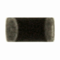
ERT-J0ER104J Panasonic - ECG, ERT-J0ER104J Datasheet - Page 8

ERT-J0ER104J
Manufacturer Part Number
ERT-J0ER104J
Description
THERMISTOR NTC 100K OHM 5% 0402
Manufacturer
Panasonic - ECG
Series
ERT-Jr
Datasheet
1.ERT-J0ER104J.pdf
(18 pages)
Specifications of ERT-J0ER104J
Resistance In Ohms @ 25°c
100K
Resistance Tolerance
±5%
B Value Tolerance
±2%
B25/50
4250K
B25/85
4300K
Operating Temperature
-40°C ~ 125°C
Power - Max
66mW
Mounting Type
Surface Mount
Package / Case
0402 (1005 Metric)
Lead Free Status / RoHS Status
Lead free / RoHS Compliant
B0/50
-
B25/75
-
B25/100
-
Lead Length
-
Other names
ERTJ0ER104J
P13703TR
P13703TR
CLASSIFICATION
SUBJECT
1.
2.
2- 1.Circuit Design
Note :
!
2-1-1. Operating Temperature and Storage Temperature
2-1-2. Operating Power
2-1-3. Environmental Restrictions
2-1-4. Measurement of Resistance
Precautions for Use
Operating Conditions and Circuit Design
・ The Maximum power that can be continuously applied under static air at
・ The constant amount power required to raise the temperature of the
【Maximum power dissipation】
【Dissipation factor】
a certain ambient temperature. The Maximum power dissipation under
ambient temperature 25°C or less is the same with the rated maximum
power dissipation, and Maximum power dissipation beyond 25°C
depends on the right Decreased power dissipation curve.
Thermistor 1°C through self heat generation under stable temperatures.
Multilayer Chip NTC Thermistors (hereafter referred to as “Thermistors”) may fail in a short circuit mode or in an
open circuit mode, when subjected to severe conditions of electrical environmental and/or mechanical stress
beyond the specified “Rating” and specified “Conditions” in the Specification, resulting in burnout, flaming or
glowing in the worst case. The following “Precautions for Safety” and “Application Notes” shall be taken in your
major consideration for use.
Dissipation factor (mW/°C) = Power consumption of Thermistor
(1) Environmental conditions
(2) Mechanical conditions
The specified “Operating Temperature Range” in the Specifications is the absolute maximum and minimum
temperature rating. Every circuit mounting a Thermistor shall be operated within the specified “Operating
Temperature Range”. The Thermistors mounted on PCB shall be stored without operating within the specified
“Storage Temperature Range” in the Specifications.
Thermistors shall not be operated in excess of the “Maximum power dissipation”.
If the Thermistors are operated beyond the specified Maximum power dissipation, it may cause burnout and/or
damage due to thermal run away.
For temperature detection applications, the accuracy may be greatly influenced by self-heat generation and
the heat dissipation of the Thermistor, even if the Thermistor is operated under the specified Maximum Power
Dissipation. Check safety and reliability in your circuit.
The Thermistors shall not be operated and/or stored under the following conditions.
The resistance of the Thermistors varies dependent on ambient temperatures and self-heating. Note the
following points when measuring resistance values of the Thermistors during inspection or when considering
them for circuits.
(1) Measurement temp : 25±0.1°C
(2) Power : 0.10 mW max.
(a) Under direct exposure to water or salt water
(b) Under conditions where water can condense and/or dew can form
(c) Under conditions containing corrosive gases such as hydrogen sulfide, sulfurous acid, chlorine and
Under severe conditions of extreme vibrations or shocks.
ammonia
Measurement in liquid (silicon oil) is recommended for a stable measurement temperature.
4 terminal measurement with a constant-current power supply is recommended.
Panasonic Electronic Devices Co., Ltd.
Common Specification (Precautions for Use)
Multilayer Chip NTC Thermistors
SPECIFICATIONS
/ Temperature rise of element
APPROVAL
Y. Sakaguti
100
50
0
-25
Decreased power dissipation curve
CHECK
T.Kawamura
25
No.
PAGE
DATE
Tem p. (deg.C)
151S-ERTJ-SS03E
Rated Maximum
Pow er Dissipation
75
May 12, 2006
1 of 7
DESIGN
125
S. Inagaki


