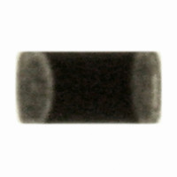
ERT-J0ER104J Panasonic - ECG, ERT-J0ER104J Datasheet - Page 9

ERT-J0ER104J
Manufacturer Part Number
ERT-J0ER104J
Description
THERMISTOR NTC 100K OHM 5% 0402
Manufacturer
Panasonic - ECG
Series
ERT-Jr
Datasheet
1.ERT-J0ER104J.pdf
(18 pages)
Specifications of ERT-J0ER104J
Resistance In Ohms @ 25°c
100K
Resistance Tolerance
±5%
B Value Tolerance
±2%
B25/50
4250K
B25/85
4300K
Operating Temperature
-40°C ~ 125°C
Power - Max
66mW
Mounting Type
Surface Mount
Package / Case
0402 (1005 Metric)
Lead Free Status / RoHS Status
Lead free / RoHS Compliant
B0/50
-
B25/75
-
B25/100
-
Lead Length
-
Other names
ERTJ0ER104J
P13703TR
P13703TR
CLASSIFICATION
SUBJECT
2- 2.Design of Printed Circuit Board
Note ;
2-2-1. Selection of Printed Circuit Boards
2-2-2. Design of Land Pattern
2-2-3. Utilization of Solder Resist
Mixed mounting
with a component with
lead wires
Arrangement
near chassis
Retro-fitting of
component with lead
wires
Lateral arrangement
Land
When the Thermistors are mounted and soldered on an “Alumina Substrate”, the substrate influences the
Thermistors’ reliability against “Temperature Cycles” and “Heat shock” due to the difference in the thermal
expansion coefficient between them. Confirm that the actual board used does not deteriorate the characteristics
of the Thermistors.
The application of solder resist is effective in preventing solder bridges and controlling the amount of solder on
PC boards.
(1) Recommended land dimensions are shown below for proper amount of solder to prevent cracking at the
[ Recommended land dimensions (Ex.) ]
(2) The size of lands shall be designed to have equal spacing between the right and left sides. If the amount of
(1) Solder resist shall be utilized to equalize the amounts of solder on both sides.
(2) Solder resist shall be used to divide the pattern for the following cases;
time of excessive stress to the Thermistors due to increased amount of solder.
solder on the right land is different from that on the left land, the component may be cracked by stress since
the side with a larger amount of solder solidifies later during cooling.
b
See the table below.
SMD
・Components are arranged closely.
・The Thermistor is mounted near a component with lead wires.
・The Thermistor is placed near a chassis.
a
Common Specification (Precautions for Use)
(a) Excessive amount
Multilayer Chip NTC Thermistors
of solder
Solder
resist
Soldering iron
Land
NG Applications and Recommended Applications
Chassis
SPECIFICATIONS
←solder
Solder (ground solder)
Z (0201)
0 (0402)
1 (0603)
Recommended Amount of Solder
NG applications
Code
(EIA)
Size
(b) Proper amount
The lead wire of
a component with
of solder
Portion to be
0.6
1.0
1.6
Lead wire of
L
Sectional view
Sectional view
Sectional view
excessively
Retro-fitted
component
Component
lead wires
soldered
Dimension
←solder
0.3
0.5
0.8
W
0.3
0.5
0.8
T
Improved applications by pattern division
(c) Insufficient amount
Solder resist
Solder resist
Solder resist
0.2 to 0.3
0.4 to 0.5
0.8 to 1.0
of solder
a
←solder
0.25 to 0.3
0.4 to 0.5
0.6 to 0.8
No.
PAGE
DATE
b
151S-ERTJ-SS03E
Sectional view
Sectional view
Sectional view
Solder resist
May 12, 2006
2 of 7
Unit: mm
0.2 to 0.3
0.4 to 0.5
0.6 to 0.8
C


