QDE-825D BANNER ENGINEERING, QDE-825D Datasheet
QDE-825D
Specifications of QDE-825D


Related parts for QDE-825D


QDE-825D Summary of contents
Page 1
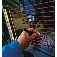
EZ-SCREEN Features • An optoelectronic safeguarding device • Standard and cascadeable models available • Compact package for smaller production machines, robust for large power presses • Creates a screen of synchronized, modulated infrared sensing beams. Choose from two resolutions, sized ...
Page 2
... Whether or not any particular EZ-SCREEN installation meets all applicable requirements depends upon factors that are beyond the control of Banner Engineering Corp. These factors include the details of how the EZ-SCREEN is applied, installed, wired, operated, and maintained the ...
Page 3
... The OSSD (Output Signal Switching Device) safety outputs are capable of performing a “handshake” communication with the Muteable Safety Stop Interface (MSSI) or Universal Safety Stop Interface (USSI) found on other Banner Engineering safety products. Banner EZ-SCREEN is a two-piece (“two-box”) system – comprising an emitter and a receiver, but no external controller. ...
Page 4
... The Diagnostic Display is used to diagnose causes of a Lockout condition (see Section 5.1). Banner Engineering Corp. Banner Engineering Corp. www.bannerengineering.com • Tel: 763.544.3164 www.bannerengineering.com • Tel: 763.544.3164 EZ-SCREEN Instruction Manual Minneapolis, U.S.A. Minneapolis, U.S.A. ...
Page 5
... EZ-SCREEN going into RUN mode. Failure to follow these instructions could result in serious bodily injury or death. Banner Engineering Corp. Banner Engineering Corp. Minneapolis, U.S.A. Minneapolis, U.S.A. • • ...
Page 6
... Diagnostic Display code meanings. Emitter 3-digit Diagnostic Display Yellow Reset Indicator Status Indicator (Red/Green) EZ-SCREEN Instruction Manual 1-digit Diagnostic Display Status Indicator (Red/Green) Banner Engineering Corp. Banner Engineering Corp. Minneapolis, U.S.A. Minneapolis, U.S.A. • • www.bannerengineering.com • Tel: 763.544.3164 www.bannerengineering.com • Tel: 763.544.3164 ...
Page 7
... Fixed blanking is easily programmed, simply by positioning the objects, flipping two DIP switches and resetting the System, as described in Section 3.4.3. Banner Engineering Corp. Banner Engineering Corp. Minneapolis, U.S.A. Minneapolis, U.S.A. • • www.bannerengineering.com • Tel: 763.544.3164 www.bannerengineering.com • ...
Page 8
... P/N 112852 rev. F P/N 112852 rev. F Emitter Defined Area EZ-SCREEN Instruction Manual Banner Engineering Corp. Banner Engineering Corp. Banner Engineering Corp. Banner Engineering Corp. Minneapolis, U.S.A. Minneapolis, U.S.A. Minneapolis, U.S.A. Minneapolis, U.S.A. • • • • www.bannerengineering.com • Tel: 763.544.3164 www.bannerengineering.com • Tel: 763.544.3164 www.bannerengineering.com • ...
Page 9
... SLSE14-150WQ8), or add “SO” for a “safety orange” painted finish, black endcaps (e.g., SLSE14-150SOQ8). Banner Engineering Corp. Banner Engineering Corp. Banner Engineering Corp. Banner Engineering Corp. Minneapolis, U.S.A. Minneapolis, U.S.A. Minneapolis, U.S.A. Minneapolis, U.S.A. ...
Page 10
... Banner Engineering Corp. Banner Engineering Corp. Banner Engineering Corp. Banner Engineering Corp. Minneapolis, U.S.A. Minneapolis, U.S.A. Minneapolis, U.S.A. Minneapolis, U.S.A. • • • • www.bannerengineering.com • Tel: 763.544.3164 www.bannerengineering.com • Tel: 763.544.3164 www.bannerengineering.com • Tel: 763.544.3164 ...
Page 11
... Single-Ended (Machine Interface) Cables (one cable for each emitter and receiver) Overmold and cables are PVC-jacketed. Cables are unterminated on one end to interface with guarded machine. Model Length Wire Number For 8-Pin Emitters and Receivers** QDE-815D 4.5 m (15') QDE-825D 8 m (25') 22 QDE-850D 15 m (50') gauge QDE-875D 23 m (75 (100') QDE-8100D ...
Page 12
... The model DEE2R-.. double-ended cables described on page 8 may be used to extend the lengths of the QD trunk, branch #1, or branch #2. (Branch #1 and branch #2 cable sections are 300 mm/1' long.) The model QDE-8..D single-ended cables may be used to extend the QD trunk for cut-to-length applications. Model Number ...
Page 13
... SLSE..-..Q5 (with Test input) EZAC-E-QE8-QS3 SLSE..-..Q8 (without Test input) EZAC-E-QE5-QS5 SLSE..-..Q5 (with Test input) Remote Reset Switch Keyed reset switch can be interconnected using cordset models QDE-8..D, DEE2R-8..D, or CSB-..M1281. EZA-RR-1 Remote reset switch with 8-pin M12/Euro-style QD Banner Engineering Corp. Banner Engineering Corp. ...
Page 14
... Height (1.58") Square (4) M10 Bolt 127 mm (5.0") Base Plate Thickness 6.4 mm (0.25") Banner Engineering Corp. Banner Engineering Corp. Banner Engineering Corp. Banner Engineering Corp. Minneapolis, U.S.A. Minneapolis, U.S.A. Minneapolis, U.S.A. Minneapolis, U.S.A. • • • • www.bannerengineering.com • Tel: 763.544.3164 www.bannerengineering.com • Tel: 763.544.3164 www.bannerengineering.com • ...
Page 15
... (2.3"). * Stainless steel reflective surface models also available by adding model number suffix “-S” (e.g., SSM-200-S); range reduction for these Banner Engineering Corp. Banner Engineering Corp. Banner Engineering Corp. Banner Engineering Corp. Minneapolis, U.S.A. Minneapolis, U.S.A. Minneapolis, U.S.A. Minneapolis, U.S.A. ...
Page 16
... C L (0.17") 39.2 mm (1.54") 58 (2.29") (1.57") Banner Engineering Corp. Banner Engineering Corp. Banner Engineering Corp. Banner Engineering Corp. Minneapolis, U.S.A. Minneapolis, U.S.A. Minneapolis, U.S.A. Minneapolis, U.S.A. • • • • www.bannerengineering.com • Tel: 763.544.3164 www.bannerengineering.com • Tel: 763.544.3164 www.bannerengineering.com • Tel: 763.544.3164 ...
Page 17
... Available in a kit that includes one M18 EZ-LIGHT, one SMB18A mounting bracket, and hardware for mounting to the side channel of an EZ-SCREEN housing (kit model * number EZA-M18RGX8PQ8). Banner Engineering Corp. Banner Engineering Corp. Banner Engineering Corp. Banner Engineering Corp. Minneapolis, U.S.A. Minneapolis, U.S.A. Minneapolis, U.S.A. Minneapolis, U.S.A. • ...
Page 18
... Part # 112852 113361 118173 113362 114189 EZ-SCREEN Instruction Manual Banner Engineering Corp. Banner Engineering Corp. Banner Engineering Corp. Banner Engineering Corp. Minneapolis, U.S.A. Minneapolis, U.S.A. Minneapolis, U.S.A. Minneapolis, U.S.A. • • • • www.bannerengineering.com • Tel: 763.544.3164 www.bannerengineering.com • Tel: 763.544.3164 www.bannerengineering.com • ...
Page 19
... Enclosure Operating Conditions Shock and Vibration Mounting Hardware Cables and Connections Certifications Banner Engineering Corp. Banner Engineering Corp. Banner Engineering Corp. Banner Engineering Corp. Minneapolis, U.S.A. Minneapolis, U.S.A. Minneapolis, U.S.A. Minneapolis, U.S.A. • • • • www.bannerengineering.com • Tel: 763.544.3164 www.bannerengineering.com • ...
Page 20
... All Other Beams 220 152 ms Banner Engineering Corp. Banner Engineering Corp. Banner Engineering Corp. Banner Engineering Corp. Minneapolis, U.S.A. Minneapolis, U.S.A. Minneapolis, U.S.A. Minneapolis, U.S.A. • • • • www.bannerengineering.com • Tel: 763.544.3164 www.bannerengineering.com • ...
Page 21
... EZA-MBK-11N stainless steel brackets for ESD model emitters and receivers. Figure 2-1. Included mounting bracket dimensions (for emitter or receiver) Banner Engineering Corp. Banner Engineering Corp. Banner Engineering Corp. Banner Engineering Corp. Minneapolis, U.S.A. Minneapolis, U.S.A. Minneapolis, U.S.A. Minneapolis, U.S.A. • • ...
Page 22
... Banner Engineering Corp. Banner Engineering Corp. Banner Engineering Corp. Banner Engineering Corp. Minneapolis, U.S.A. Minneapolis, U.S.A. Minneapolis, U.S.A. Minneapolis, U.S.A. • • • • www.bannerengineering.com • Tel: 763.544.3164 www.bannerengineering.com • ...
Page 23
... Additional guarding may be required; see Separation Distance, Section 3.1.1, and Pass-Through Hazards, Section 3.1.2, and Supplemental Safeguarding, Section 3.1.4. Banner Engineering Corp. Banner Engineering Corp. Minneapolis, U.S.A. Minneapolis, U.S.A. • • ...
Page 24
... Determine Correct Stop Time Notice Regarding MPCEs by OSHA) manufacturer; plus 20% safety factor; plus 20 ms for interface module IM-T-9A response) an SLSP14-600 EZ-SCREEN System) Banner Engineering Corp. Banner Engineering Corp. Minneapolis, U.S.A. Minneapolis, U.S.A. • • www.bannerengineering.com • Tel: 763.544.3164 www.bannerengineering.com • Tel: 763.544.3164 ...
Page 25
... Failure to observe this warning could result in serious bodily injury or death. Banner Engineering Corp. Banner Engineering Corp. Minneapolis, U.S.A. Minneapolis, U.S.A. • • www.bannerengineering.com • Tel: 763.544.3164 www.bannerengineering.com • ...
Page 26
... Figure 3-5. Examples of correct emitter / receiver orientation EZ-SCREEN Instruction Manual b. Emitter and receiver not parallel to each other Problem: Reduced excess gain b. Both cable ends up Banner Engineering Corp. Banner Engineering Corp. Minneapolis, U.S.A. Minneapolis, U.S.A. • • www.bannerengineering.com • Tel: 763.544.3164 www.bannerengineering.com • Tel: 763.544.3164 ...
Page 27
... At installed operating range (R): d=0.0437 × ft) Operating range 0 (4" to 10'): d = 0.13 m (5") Operating range > > 10’): d = 0.0437 × ft) Figure 3-6. Adjacent reflective surfaces Banner Engineering Corp. Banner Engineering Corp. Minneapolis, U.S.A. Minneapolis, U.S.A. • • www.bannerengineering.com • Tel: 763.544.3164 www.bannerengineering.com • Tel: 763.544.3164 Installation and Alignment 3 ...
Page 28
... Receiver 3 d. Multiple pairs in a horizontal plane Scan Code 2 Figure 3-8. Installation of multiple pairs; alternate emitters and receivers to avoid optical crosstalk. Banner Engineering Corp. Banner Engineering Corp. www.bannerengineering.com • Tel: 763.544.3164 www.bannerengineering.com • Tel: 763.544.3164 EZ-SCREEN Instruction Manual Scan Code 1 Emitter ...
Page 29
... End-Mounted Side-Mounted (Two center brackets may be substituted) Fig ure 3-9. Emit ter and re ceiv er mounting hardware Banner Engineering Corp. Banner Engineering Corp. Minneapolis, U.S.A. Minneapolis, U.S.A. • • www.bannerengineering.com • Tel: 763.544.3164 www.bannerengineering.com • Tel: 763.544.3164 ...
Page 30
... Vertical Installations – verify that: • Distance X at the emitter and receiver are equal. • Both sensors are level/plumb (check both the side and face). • D efined area is square. Check diagonal measurements if possible (Diagonal A = Diagonal B). Banner Engineering Corp. Banner Engineering Corp. Minneapolis, U.S.A. Minneapolis, U.S.A. • • www.bannerengineering.com • Tel: 763.544.3164 www.bannerengineering.com • Tel: 763.544.3164 ...
Page 31
... AWG* 150 100 75 * QDE-...D cables, see table 2.2 See Section 7.4 for cascade installations. NOTE: Maximum cable lengths are intended to ensure that adequate power is available to the EZ-SCREEN System when the supply is operating at +24V dc – 15%. WARNING . . . Proper Electrical Hookup ...
Page 32
... NOTE: If the Test input is open, the 3-digit Diagnostic Display will indicate the total number of beams in the system (minus one) and all Zone indicators will be Red. Banner Engineering Corp. Banner Engineering Corp. www.bannerengineering.com • Tel: 763.544.3164 www.bannerengineering.com • Tel: 763.544.3164 EZ-SCREEN Instruction Manual Minneapolis, U ...
Page 33
... The MSM... and SSM-... rear-surface glass mirrors are rated at 85% efficiency. Thus, excess gain and sensing range are reduced when using mirrors; see Section 3.1.7. Banner Engineering Corp. Banner Engineering Corp. Minneapolis, U.S.A. Minneapolis, U.S.A. • • ...
Page 34
... Instruction Manual Maximum Size Resulting of Undetected Resolution Objects (Not applicable (0.55") 8.5 mm (0.34" (1.18") (Not applicable (1.18" (0.67" (2.36") Use of Reduced Resolution Banner Engineering Corp. Banner Engineering Corp. Minneapolis, U.S.A. Minneapolis, U.S.A. • • www.bannerengineering.com • Tel: 763.544.3164 www.bannerengineering.com • Tel: 763.544.3164 ...
Page 35
... ON (2-beam) Model STP-14 Cascaded systems: To test a cascaded system, each light screen must be tested individually, while monitoring the status indicator on the first receiver in the cascade. Banner Engineering Corp. Banner Engineering Corp. Minneapolis, U.S.A. Minneapolis, U.S.A. • • www.bannerengineering.com • Tel: 763.544.3164 www.bannerengineering.com • Tel: 763.544.3164 1 ...
Page 36
... Always disconnect all power from the EZ-SCREEN System and the guarded machine before making any connections or replacing any component. Use extreme caution to avoid electrical shock at all times. Banner Engineering Corp. Banner Engineering Corp. www.bannerengineering.com • Tel: 763.544.3164 www.bannerengineering.com • Tel: 763.544.3164 EZ-SCREEN Instruction Manual Minneapolis, U ...
Page 37
... EZ-SCREEN. Banner Engineering Corp. Banner Engineering Corp. Minneapolis, U.S.A. Minneapolis, U.S.A. • • ...
Page 38
... EDM Don’t Care Don’t Care Open Figure 3-16. One-channel EDM status, with respect to safety output Banner Engineering Corp. Banner Engineering Corp. www.bannerengineering.com • Tel: 763.544.3164 www.bannerengineering.com • Tel: 763.544.3164 EZ-SCREEN Instruction Manual Don’t Care Don’t Care 250 ms 250 ms Max ...
Page 39
... NOTE: For EZ-SCREEN receivers with a date code prior to 0834, the monitoring contacts must always close within 200 milliseconds of the corresponding OSSD state change (turning OFF lockout will occur. Banner Engineering Corp. Banner Engineering Corp. Minneapolis, U.S.A. Minneapolis, U.S.A. • • www.bannerengineering.com • Tel: 763.544.3164 www.bannerengineering.com • ...
Page 40
... The operation of the EZ-SCREEN with the guarded machine must be verified before the combined EZ-SCREEN and machine may be put into service this, a Qualified Person must perform the Commissioning Checkout Procedure described in Section 6.2. Individual 8-wire Cordsets Emitter QDE-8..D Cables Bn Or/ Gn/Ye Vi Figure 3-19 ...
Page 41
... Bu (# (#5) OSSD1 Wh (#4) OSSD2 Vi (#8) Reset* Or (#3) EDM1 Or/Bk (#2) EDM2 *Trip (auto reset) – Not connected See Table 2.2 for further † QDE-8..D cable information. Installation and Alignment Overview 0V dc FSD 2 +24V Jumper SC22-3 Safety Controller P/N 112852 rev. F P/N 133487 ...
Page 42
... Trip (auto reset) — Not connected *** Other interfacing modules and solutions available, see Section 2.3 or the Banner Safety Catalog. † See Table 2.2 for further QDE-8D cable information. Fig ure 3-23. Generic hookup – Interface Module (1-Channel or 2-Channel EDM, manual reset) 40 ...
Page 43
... After configuration settings are verified/set, the access cover must be fully closed (snap shut) to maintain IP ratings. Other than Scan Code, all configuration settings should be changed only when the System is OFF. Banner Engineering Corp. Banner Engineering Corp. Minneapolis, U.S.A. Minneapolis, U.S.A. • • ...
Page 44
... Emitter Resets In the rare occurrence that an emitter requires a reset, power the sensor down, then power it up. Emitter resets are needed only if a Lockout occurs. Banner Engineering Corp. Banner Engineering Corp. www.bannerengineering.com • Tel: 763.544.3164 www.bannerengineering.com • Tel: 763.544.3164 EZ-SCREEN Instruction Manual Minneapolis, U ...
Page 45
... NOTE: If beam 1 is blocked, Zone indicators 2-8 will be OFF, because beam 1 provides the synchronization signal for all the beams. Flashing if Reduced Resolution is enabled. † Figure 4-4. Receiver status indicator operation (Trip Output configured) Banner Engineering Corp. Banner Engineering Corp. Minneapolis, U.S.A. Minneapolis, U.S.A. • • ...
Page 46
... Flashing Continues Continues previous previous reading reading Displays error code (see Section 5.1) inverted label Banner Engineering Corp. Banner Engineering Corp. Minneapolis, U.S.A. Minneapolis, U.S.A. • • www.bannerengineering.com • Tel: 763.544.3164 www.bannerengineering.com • Tel: 763.544.3164 EZ-SCREEN OSSD Outputs OFF OFF ...
Page 47
... Reset: ON Status: Green Config: Latch Display: L OSSDs: ON Reset: ON Status: Green Figure 4-7. Cascade indicator status conditions Banner Engineering Corp. Banner Engineering Corp. Minneapolis, U.S.A. Minneapolis, U.S.A. • • www.bannerengineering.com • Tel: 763.544.3164 www.bannerengineering.com • Tel: 763.544.3164 EZ-SCREEN Cascade Diagnostics Condition OSSDs ...
Page 48
... Verify Proper Operation It is the user’s responsibility to verify proper operation regular basis, as instructed in Section 6. Failure to correct such problems can result in serious bodily injury or death. Banner Engineering Corp. Banner Engineering Corp. www.bannerengineering.com • Tel: 763.544.3164 www.bannerengineering.com • Tel: 763.544.3164 EZ-SCREEN Instruction Manual Minneapolis, U ...
Page 49
... EZ-SCREEN is set for Latch Output, a manual reset, as described in Section 4.3, is required to resume full operation. Emitter Reset Power the sensor down, wait a second or two, and then power it up. Banner Engineering Corp. Banner Engineering Corp. Minneapolis, U.S.A. Minneapolis, U.S.A. • • www.bannerengineering.com • Tel: 763.544.3164 www.bannerengineering.com • Tel: 763.544.3164 Troubleshooting and Maintenance WARNING ...
Page 50
... Section 3.5.3. • If the error continues, check for noise on the EDM inputs (see Section 5.3). Banner Engineering Corp. Banner Engineering Corp. www.bannerengineering.com • Tel: 763.544.3164 www.bannerengineering.com • Tel: 763.544.3164 EZ-SCREEN Instruction Manual Minneapolis, U ...
Page 51
... This error can occur due to excessive levels of electrical noise. Flashing Cascade Input Simultaneity Operation of channels A and B mismatch > 3 seconds. Banner Engineering Corp. Banner Engineering Corp. Minneapolis, U.S.A. Minneapolis, U.S.A. • • www.bannerengineering.com • Tel: 763.544.3164 www.bannerengineering.com • Tel: 763.544.3164 Troubleshooting and Maintenance Cause of Error and Appropriate Action • ...
Page 52
... The 3-digit display will show a numerical value equal to one less than the total number of beams. For example array has 50 beams total, the display would show 49. Figure 5-1. TEST mode status indicators Banner Engineering Corp. Banner Engineering Corp. www.bannerengineering.com • Tel: 763.544.3164 www.bannerengineering.com • Tel: 763.544.3164 EZ-SCREEN Instruction Manual ...
Page 53
... Should it become necessary to return an EZ-SCREEN component to the factory, please do the following: 1. Contact the Banner Factory Application Engineering group at the address or numbers listed below: Banner Engineering Corp., Application Engineering Group 9714 Tenth Avenue North Minneapolis, MN 55441 Phone: 763.544.3164 or Toll-Free (US only): 888 ...
Page 54
... If the EZ-SCREEN is configured for Manual Power-Up, the Yellow Status indicator will be double-flashing. Perform a manual reset (close the reset switch for 1 seconds, then open the switch). Banner Engineering Corp. Banner Engineering Corp. www.bannerengineering.com • Tel: 763.544.3164 www.bannerengineering.com • Tel: 763.544.3164 EZ-SCREEN Instruction Manual Minneapolis, U ...
Page 55
... Refer to the procedure detailed on the Daily Checkout card (Banner part number 113361 for SLS.. models, P/N 118173 for SLSC.. models) in the lit packet included with the receiver. If the Daily Checkout card is missing, contact Banner Engineering or download at www.bannerengineering.com 6.4 Semi-Annual (Six-Month) Checkout ...
Page 56
... The terminator plug must be used on the receiver in a stand- alone system, and on the last receiver in a multiple-system cascade or, a QDE2R4-8..D cable interfaced with an E-stop or other hard contacts (see Sections 7.8 and 7.9). Available single-ended, double-ended, and splitter cables are listed in Section 2.3. Cable lengths are limited – ...
Page 57
... Cascadeable Emitter and Receiver Models – Resolution For cabling options, see Section 2.3. Machine interface/power cables (one per end sensor, two per pair): Use QDE-..D cables. Sensor interconnect cables (one per cascaded sensor, two per pair): Use DEE2R-..D cables. Defined Area ...
Page 58
... Cascadeable Emitter and Receiver Models – Resolution For cabling options, see Section 2.3. Machine interface/power cables (one per end sensor, two per pair): Use QDE-..D cables. Sensor interconnect cables (one per cascaded sensor, two per pair): Use DEE2R-..D cables. Defined Area ...
Page 59
... Machine Interface Cable (L1): 15' Sensor Interconnect Cable (L2): 175' (Using one 100' and one 75' DEE2R cables) or 100' or shorter using single cables Figure 7-2. Cable length options for two cascaded light screens Machine Interface Cable (L1) QDE-..D Recommended cable pairing per side of cascaded system L2 Max. L2* 115' Max ...
Page 60
... A common installation example is one that protects two areas of a machine (e.g., the front and back of a power press) and uses four EZ-SCREEN pairs to create two “L”-shaped sensing fields. Machine Interface Cable (L1) QDE-..D Recommended cable pairing per side of cascaded system Max. L3* Sensor ...
Page 61
... WARNING . . . Proper Installation The user must comply with all instructions within Section 3 for proper installation. See Sections 7.2 and 3.1.1 for complete information. Banner Engineering Corp. Banner Engineering Corp. Minneapolis, U.S.A. Minneapolis, U.S.A. • • www.bannerengineering.com • Tel: 763.544.3164 www.bannerengineering.com • Tel: 763.544.3164 ...
Page 62
... Receivers EZ-SCREEN Position # Individual Response Time EZ-SCREEN Position # Individual Response Time EZ-SCREEN Position #1 Individual Response Time Machine Machine Control Control Banner Engineering Corp. Banner Engineering Corp. Minneapolis, U.S.A. Minneapolis, U.S.A. • • www.bannerengineering.com • Tel: 763.544.3164 www.bannerengineering.com • Tel: 763.544.3164 EZ-SCREEN ...
Page 63
... If not, a receiver may synchronize to the signal from the wrong emitter, reducing the safety function of the light screen. This situation will be discovered by performing the trip test (see Section 3.4.3). Banner Engineering Corp. Banner Engineering Corp. Minneapolis, U.S.A. Minneapolis, U.S.A. • • www.bannerengineering.com • Tel: 763.544.3164 www.bannerengineering.com • ...
Page 64
... E-Stop awg QDE2R4-8..D Cable Pinout* Pin #1 ― Brown (Ch 1a) Pin #5 ―n.c. Pin #2 ― Black (Ch 1b) Pin #6 ―n.c. Pin #3 ― Blue (Ch 2b) Pin #7 ―n.c. Pin #4 ―n.c. Pin #8 ― White (Ch 2a) * Standard M12 / Euro-style cables (8-pin male QD) can also be used, although pin number / wire color must be verified ...
Page 65
... NOTE: This application is considered to meet or exceed requirements for OSHA control reliability and safety categories 4 per Bn ISO 13849- QDE2R4-8..D Cable Pinout* Pin #1 ― Brown (Ch 1a) Pin #5 ―n.c. Pin #2 ― Black (Ch 1b) Pin #6 ―n.c. Pin #3 ― Blue (Ch 2b) Pin #7 ―n.c. Pin #4 ―n.c. Pin #8 ― White (Ch 2a) ...
Page 66
... EZ-SCREEN considers the failure to be corrected. With the input requirements apparently satisfied, the EZ-SCREEN allows a reset. This system is no Open QDE2R4-8..D Cable Pinout* Pin #1 ― Brown (Ch 1a) Pin #5 ―n.c. Pin #2 ― Black (Ch 1b) Pin #6 ―n.c. Pin #3 ― Blue (Ch 2b) Pin #7 ―n.c. Pin #4 ―n.c. ...
Page 67
... European Union (EU) Directives and the associated safety standards. Clutch: A mechanism that, when engaged, transmits torque to impart motion from a driving member to a driven member. Banner Engineering Corp. Banner Engineering Corp. Minneapolis, U.S.A. Minneapolis, U.S.A. • • www.bannerengineering.com • Tel: 763.544.3164 www.bannerengineering.com • ...
Page 68
... Point of Operation: The location of a machine where material or a workpiece is positioned and a machine function is performed upon it. Banner Engineering Corp. Banner Engineering Corp. www.bannerengineering.com • Tel: 763.544.3164 www.bannerengineering.com • Tel: 763.544.3164 EZ-SCREEN Instruction Manual Minneapolis, U.S.A. ...
Page 69
... Banner safety light screen systems and safety modules are self- checking. Banner Engineering Corp. Banner Engineering Corp. Minneapolis, U.S.A. Minneapolis, U.S.A. • • www.bannerengineering.com • Tel: 763.544.3164 www.bannerengineering.com • ...
Page 70
... Notes Overview 68 68 P/N 112852 rev. F P/N 133487 EZ-SCREEN Instruction Manual Banner Engineering Corp. Banner Engineering Corp. Minneapolis, U.S.A. Minneapolis, U.S.A. • • www.bannerengineering.com • Tel: 763.544.3164 www.bannerengineering.com • Tel: 763.544.3164 ...
Page 71
... EZ-SCREEN Instruction Manual Banner Engineering Corp. Banner Engineering Corp. Minneapolis, U.S.A. Minneapolis, U.S.A. • • www.bannerengineering.com • Tel: 763.544.3164 www.bannerengineering.com • Tel: 763.544.3164 Notes Overview 69 69 P/N 112852 rev. F P/N 133487 ...
Page 72
... Notes Overview 70 70 P/N 112852 rev. F P/N 133487 EZ-SCREEN Instruction Manual Banner Engineering Corp. Banner Engineering Corp. Minneapolis, U.S.A. Minneapolis, U.S.A. • • www.bannerengineering.com • Tel: 763.544.3164 www.bannerengineering.com • Tel: 763.544.3164 ...
Page 73
The list of standards below is included as a convenience for users of this Banner product. Inclusion of the standards below does not imply The list of standards below is included as a convenience for users of this Banner product. ...
Page 74
... WARRANTY: Banner Engineering Corp. warrants its products to be free from defects for one year. Banner Engineering Corp. will repair or replace, free of charge, any product of its manufacture found to be defective at the time it is returned to the factory during the warranty period. This warranty does not cover damage or liability for the improper application of Banner products ...