QDE-825D BANNER ENGINEERING, QDE-825D Datasheet - Page 3
QDE-825D
Manufacturer Part Number
QDE-825D
Description
Safety Light Curtain
Manufacturer
BANNER ENGINEERING
Datasheet
1.QDE-815D.pdf
(74 pages)
Specifications of QDE-825D
Light Curtain Type
Safety
Accessory Type
Machine Interface Cable
For Use With
EZ-Screen Safety Light Screen


EZ-SCREEN
Instruction Manual
The Banner EZ-SCREEN provides a redundant, microprocessor-
controlled, opposed-mode optoelectronic “curtain of light,” or
“safety light screen.” It typically is used for point-of-operation
safeguarding, and is suited to safeguard a variety of machinery.
EZ-SCREEN is extensively FMEA (Failure Mode and Effects
Analysis) tested to establish an extremely high degree of
confidence that when properly installed, no system component
will (even if it should fail) cause a failure to danger.
In typical operation, if any part of an operator’s body (or any
opaque object) of more than a pre-determined cross section
is detected, the OSSD solid-state safety outputs will turn off.
These safety outputs are connected to the guarded machine’s
Final Switching Devices (FSDs) that control the primary control
elements (MPCEs), which immediately stop the motion of the
guarded machine.
The OSSD (Output Signal Switching Device) safety outputs
are capable of performing a “handshake” communication with
the Muteable Safety Stop Interface (MSSI) or Universal Safety
Stop Interface (USSI) found on other Banner Engineering safety
products.
Banner EZ-SCREEN is a two-piece (“two-box”) system –
comprising an emitter and a receiver, but no external controller.
The External Device Monitoring (EDM) function ensures the
fault detection capability required by U.S. Control Reliability and
ISO13849-1 Categories 3 and 4 without a third box, a controller
or a “smart” (i.e., self-checking) safety module required of
systems without EDM.
An auxiliary (aux.) output may be used to signal the state of the
OSSDs to a process controller; see Section 1.4.3.
Emitters have a row of synchronized modulated infrared
(invisible) light-emitting diodes (LEDs) in a compact rectangular
metal housing. Receivers have a corresponding row of
synchronized photodetectors. The dimensions of the light screen
created by the emitter and receiver are called the “defined
area”; its width and height are determined by the length of the
sensor pair and the distance between them. The maximum
range is dependent on the resolution; range decreases if corner
mirrors are used. Emitter and receiver pairs with 14 mm (0.55")
resolution have a maximum range of 6 m (20'), and pairs with 30
mm (1.18") resolution have a maximum range of 18 m (60').
1. System Overview
1.1 Introduction
Banner Engineering Corp.
Banner Engineering Corp.
www.bannerengineering.com • Tel: 763.544.3164
www.bannerengineering.com • Tel: 763.544.3164
•
•
Minneapolis, U.S.A.
Minneapolis, U.S.A.
Electrical connections are made through M12 (or Euro-style)
quick-disconnects. Some emitter models have a 5-pin connector
for power and the Test function. Other emitters and all receivers
have an 8-pin connector for power, ground, inputs and outputs.
Functions such as Trip/Latch select, Display Invert, Cascading,
Fixed Blanking, Reduced Resolution (Floating Blanking), Scan
Code select, and External Device Monitoring are described in
Section 1.4. All models require a supply voltage of +24V dc
±15%. See Section 2.4 for interfacing solutions.
Both emitter and receiver feature 7-segment Diagnostic
Displays and individual LEDs to provide continuous indication
of the EZ-SCREEN’s operating status, configuration and error
conditions. See Section 1.4.7 for more information.
This manual contains numerous WARNING and CAUTION
statements. Warnings refer to situations that could lead to
significant or serious personal injury or death. Cautions refer to
situations that could lead to slight personal injury or potential
damage to equipment.
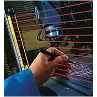
Figure 1-1. A typical EZ-SCREEN application: weld cell
Overview
Overview
P/N 112852 rev. F
P/N 133487
1
1
Related parts for QDE-825D
Image
Part Number
Description
Manufacturer
Datasheet
Request
R

Part Number:
Description:
CDS EU 8 F RT 30 DSF8X22 1 GN B 30.0 63.5 12.7 5.46 N
Manufacturer:
BANNER ENGINEERING
Part Number:
Description:
CDS EU 8 F RT 5.0 DSF8x22 1 GN B 5.00 63.5 12.7 5.46 N
Manufacturer:
BANNER ENGINEERING
Part Number:
Description:
CDS EU 8 F RT 8.0 DSF8x22 1 GN B 8.00 63.5 12.7 5.46 N
Manufacturer:
BANNER ENGINEERING
Part Number:
Description:
CDS EU 8 F ST 15
Manufacturer:
BANNER ENGINEERING
Datasheet:
Part Number:
Description:
CDS EU 8 F RT 15 DSF8x22 1 GN B 15.0 63.5 12.7 5.46 N
Manufacturer:
BANNER ENGINEERING
Part Number:
Description:
CDS EU 8 F RT 23 DSF8X22 1 GN B 23.0 63.5 12.7 5.46 N
Manufacturer:
BANNER ENGINEERING

Part Number:
Description:
Safety Light Curtain
Manufacturer:
BANNER ENGINEERING
Datasheet:

Part Number:
Description:
Photoelectric Sensor
Manufacturer:
BANNER ENGINEERING
Datasheet:

Part Number:
Description:
Programmable Indicator Light
Manufacturer:
BANNER ENGINEERING
Datasheet:
Part Number:
Description:
INDICATOR LED PANEL 50MM GRN/RED/YEL 30V
Manufacturer:
BANNER ENGINEERING
Datasheet:
Part Number:
Description:
Programmable Indicator Light
Manufacturer:
BANNER ENGINEERING
Datasheet: