QDE-825D BANNER ENGINEERING, QDE-825D Datasheet - Page 44
QDE-825D
Manufacturer Part Number
QDE-825D
Description
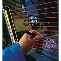
Safety Light Curtain
Manufacturer
BANNER ENGINEERING
Datasheet
1.QDE-815D.pdf
(74 pages)
Specifications of QDE-825D
Light Curtain Type
Safety
Accessory Type
Machine Interface Cable
For Use With
EZ-Screen Safety Light Screen


42
42
Accessing the Configuration Panel
To open the access cover for DIP switch configuration:
1. Remove the security plate using the special tool supplied.
2. Using a small flat blade screwdriver or the security plate tool,
3. Pivot the screwdriver against the bevel until the access cover
4. To close the access cover, simply push cover into place (it will
5. If required, replace the security plate with tamper-resistant
It is important to snap-close the cover to maintain the sensors’
IP 65 environmental rating. In the event an access cover is lost
or damaged, it can be re-ordered (see Section 2.5, Replacement
Parts). It is recommended for installations subject to shock and
vibration, that the security plate be reinstalled.
Figure 4-2. Accessing the configuration switches
P/N 133487
P/N 112852 rev. F
“snap” into place). The access cover has been designed to be
removable, so if it should come off, simply snap it back onto
the hinge and close it.
push the plastic tab on the access cover inwards at a 45°
angle.
pops open.
screws provided, using the same supplied tool.
System Operation
Overview
1. Remove Security Plate
2. Open Access
Cover
Resetting the System
System resets are performed using an external reset switch.
This switch must be located outside the guarded area, and must
not be within reach from within the guarded area (see Section
3.1.3). Its location should provide a clear view of the entire
safeguarded area. If any hazardous areas are not in view from
the switch location, additional means of safeguarding must be
provided. The switch should be protected from accidental or
unintended actuation (e.g., through the use of rings or guards).
If supervisory control of the reset switch is required, a key
switch may be used, with the key kept in the possession of a
Designated or Qualified Person. Using a key switch will also
provide some level of personal control, since the key may be
removed from the switch. This will hinder a reset while the key
is under the control of an individual, but must not be relied upon
solely to guard against accidental or unauthorized reset. Spare
keys in the possession of others or additional personnel entering
the safeguarded area unnoticed may create a hazardous
situation.
Receiver Resets
The EZ-SCREEN receiver has a Reset input, pin 8 (Violet wire),
that allows the System to be manually reset.
The EZ-SCREEN requires a manual reset to clear a Latch
condition and resume operation following a stop command.
Internal Lockout conditions also require a manual reset to return
the System to RUN mode after the failure has been corrected
and the input correctly cycled.
Receiver manual resets are required in the following
situations:
• T rip Output operation – only after a System Lockout (see
• Latch Output operation – at power-up, after each Latch
Reset Routine
To reset the receiver, close the reset switch for 1/4 to 2 seconds,
then open the switch. (If reset switch model MGA-KS0-1, listed
in Section 2, is used, turn the key 1/4 turn clockwise to close;
turn counterclockwise, back to its original position, to open.)
NOTE: Closing the reset switch too long will cause the System
Emitter Resets
In the rare occurrence that an emitter requires a reset, power
the sensor down, then power it up. Emitter resets are needed
only if a Lockout occurs.
4.3 Reset Procedures
Section 5 for causes).
condition occurs, and after a System Lockout.
to ignore the reset request; the switch must be closed
from 1/4 second to 2 seconds, but no longer.
Banner Engineering Corp.
Banner Engineering Corp.
www.bannerengineering.com • Tel: 763.544.3164
www.bannerengineering.com • Tel: 763.544.3164
Instruction Manual
•
•
Minneapolis, U.S.A.
Minneapolis, U.S.A.
EZ-SCREEN
Related parts for QDE-825D
Image
Part Number
Description
Manufacturer
Datasheet
Request
R

Part Number:
Description:
CDS EU 8 F RT 30 DSF8X22 1 GN B 30.0 63.5 12.7 5.46 N
Manufacturer:
BANNER ENGINEERING
Part Number:
Description:
CDS EU 8 F RT 5.0 DSF8x22 1 GN B 5.00 63.5 12.7 5.46 N
Manufacturer:
BANNER ENGINEERING
Part Number:
Description:
CDS EU 8 F RT 8.0 DSF8x22 1 GN B 8.00 63.5 12.7 5.46 N
Manufacturer:
BANNER ENGINEERING
Part Number:
Description:
CDS EU 8 F ST 15
Manufacturer:
BANNER ENGINEERING
Datasheet:
Part Number:
Description:
CDS EU 8 F RT 15 DSF8x22 1 GN B 15.0 63.5 12.7 5.46 N
Manufacturer:
BANNER ENGINEERING
Part Number:
Description:
CDS EU 8 F RT 23 DSF8X22 1 GN B 23.0 63.5 12.7 5.46 N
Manufacturer:
BANNER ENGINEERING

Part Number:
Description:
Safety Light Curtain
Manufacturer:
BANNER ENGINEERING
Datasheet:

Part Number:
Description:
Photoelectric Sensor
Manufacturer:
BANNER ENGINEERING
Datasheet:

Part Number:
Description:
Programmable Indicator Light
Manufacturer:
BANNER ENGINEERING
Datasheet:
Part Number:
Description:
INDICATOR LED PANEL 50MM GRN/RED/YEL 30V
Manufacturer:
BANNER ENGINEERING
Datasheet:
Part Number:
Description:
Programmable Indicator Light
Manufacturer:
BANNER ENGINEERING
Datasheet: