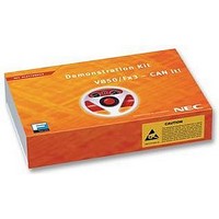
V850FX3-CANIT NEC, V850FX3-CANIT Datasheet - Page 17

V850FX3-CANIT
Manufacturer Part Number
V850FX3-CANIT
Description
STARTER KIT, 32BIT, CAN
Manufacturer
NEC
Datasheet
1.V850FX3-CANIT.pdf
(84 pages)
Specifications of V850FX3-CANIT
Svhc
No SVHC (18-Jun-2010)
Development Tool Type
Starter Kit
Kit Features
Easy To Use Device Demonstration Capabilities, TK-V850 Debugging, N-Wire Debugging
Mcu Supported Families
V850ES/Fx3
Silicon Manufacturer
NEC
Core Architecture
RISC
Kit Contents
Board
Features
N-Wire Debugging, Character LCD Module, USB Interface
V850ES/Fx3 – CAN it!
3.4.2 TK-V850 / FPL mode selection switch SW4/S2
SW4 switch S2 selects the TK-V850 On-Board debugging or FPL FLASH programming mode. Setting
SW4/S2 to OFF enables the TK-V850 On-Board debug function. Switching SW4/S2 to ON allows On-
Board FLASH programming by using the FPL FLASH programmer software.
For more details on how to configure V850ES/Fx3 – CAN it! in order to use On-Chip debugging please
refer to CHAPTER 5, ON-CHIP DEBUGGING.
3.4.3 UART/ LIN mode selection SW4/S3
SW4 switch S3 controls the serial communication mode of V850ES/Fx3 – CAN it! board. Setting SW4/S3
to OFF connects the UARTD0 receive and transmit signals to the FT232 interface lines and the UARTD2
receive and transmit signals to the TJA1020 LIN transceiver. Switching SW4/S3 to ON connects the
UARTD0 and UARTD2 signals vice versa.
By using the TK-V850 debugging / FPL FLASH programming mode set switch SW4/S3 to OFF. UARTD0
is reserved as communication channel for On-Board debugging or FLASH programming and can not be
used by a user program.
3.4.4 User switch SW4/S4
SW4 switch S4 is connected to port P911 of the V850ES/FG3 device. This switch can be freely used by
the user software. Switching SW4/S4 to ON applies V
3.5 LIN plug JP1
JP1 is a 3 pin connector for the LIN bus, connected to the transceiver TJA1020.
OFF
ON
1
2
3
SW4, S3
OFF
ON
JP1
OFF
ON
SW4, S2
SW4, S4
BAT
LIN
GND
Table 3: TK-V850 / FPL mode selection switch SW4/S2
Table 4: UART/ LIN mode selection SW4/S3
Table 5: User switch SW4/S4
Signal
User’s Manual U18560EE1V0UM00
UARTD0 connected to FT232 UART chip
UARTD2 connected to TJA1020 LIN transceiver
UARTD0 connected to TJA1020 LIN transceiver
UARTD2 connected to FT232 UART chip
Table 6: LIN plug JP1
Reference voltage for the LIN bus level
LIN bus line
Ground
FPL FLASH programming mode
TK-V850 debugging mode
V
V
Operation mode
Operation Mode
SS
CC
SS
to port P911.
V850ES/FG3
applied to P911
applied to P911
Description
17


