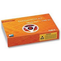
V850FX3-CANIT NEC, V850FX3-CANIT Datasheet - Page 9

V850FX3-CANIT
Manufacturer Part Number
V850FX3-CANIT
Description
STARTER KIT, 32BIT, CAN
Manufacturer
NEC
Datasheet
1.V850FX3-CANIT.pdf
(84 pages)
Specifications of V850FX3-CANIT
Svhc
No SVHC (18-Jun-2010)
Development Tool Type
Starter Kit
Kit Features
Easy To Use Device Demonstration Capabilities, TK-V850 Debugging, N-Wire Debugging
Mcu Supported Families
V850ES/Fx3
Silicon Manufacturer
NEC
Core Architecture
RISC
Kit Contents
Board
Features
N-Wire Debugging, Character LCD Module, USB Interface
V850ES/Fx3 – CAN it!
List of Figures
Figure 1: V850ES/Fx3 – CAN it! system configuration ...............................................................................14
Figure 2: V850ES/Fx3 – CAN it! baseboard connectors, switches and LED’s ...........................................15
Figure 3: Connector CN6, USB Mini-B Type Host Connector Pin Configuration........................................18
Figure 4: V850ES/Fx3 – CAN it! CPU module components .......................................................................23
Figure 5: CAN transceivers .........................................................................................................................25
Figure 6: Configuration for On-Chip debugging ..........................................................................................27
Figure 7: Add New Hardware Wizard (Windows 98SE).............................................................................31
Figure 8: Search Method (Windows 98SE).................................................................................................31
Figure 9: Search Location Specification (Windows 98SE)..........................................................................32
Figure 10: Checking Driver to Be Installed (Windows 98SE)......................................................................32
Figure 11: Installation Completion (Windows 98SE)...................................................................................33
Figure 12: Found New Hardware Wizard 1 (Windows 2000)......................................................................33
Figure 13: Search Method 1 (Windows 2000).............................................................................................34
Figure 14: Driver File Location 1 (Windows 2000) ......................................................................................34
Figure 15: Address Specification 1 (Windows 2000) ..................................................................................35
Figure 16: Driver File Search 1 (Windows 2000) ........................................................................................35
Figure 17: USB Driver Installation Completion 1 (Windows 2000) .............................................................36
Figure 18: Found New Hardware Wizard 2 (Windows 2000)......................................................................36
Figure 19: Search Method 2 (Windows 2000).............................................................................................37
Figure 20: Driver File Location 2 (Windows 2000) ......................................................................................37
Figure 21: Address Specification 2 (Windows 2000) ..................................................................................38
Figure 22: Driver File Search 2 (Windows 2000) ........................................................................................38
Figure 23: USB Driver Installation Completion 2 (Windows 2000) .............................................................39
Figure 24: Found New Hardware Wizard 1 (Windows XP).........................................................................39
Figure 25: Search Location Specification 3 (Windows XP).........................................................................40
Figure 26: Windows XP Logo Testing 3 (Windows XP) ..............................................................................40
Figure 27: USB Driver Installation Completion 1 (Windows XP).................................................................41
Figure 28: Found New Hardware Wizard 2 (Windows XP).........................................................................41
Figure 29: Search Location Specification 2 (Windows XP).........................................................................42
Figure 30: Windows XP Logo Testing 2 (Windows XP) ..............................................................................42
Figure 31: USB Serial Port2 Driver Installation Completion (Windows XP)................................................43
Figure 32: Device Manager .........................................................................................................................44
Figure 33: Driver Uninstallation ...................................................................................................................45
Figure 34: Driver Uninstaller........................................................................................................................45
Figure 35: Completion of Driver Uninstallation............................................................................................46
Figure 36: GUI Software Main Window .......................................................................................................47
Figure 37: Toolbar Buttons ..........................................................................................................................48
Figure 38: [File] Menu..................................................................................................................................49
Figure 39: HEX File Selection Window .......................................................................................................49
Figure 40: [Device] Menu ............................................................................................................................50
Figure 41: Device Setup Window - Standard ..............................................................................................52
Figure 42: Setup Window - Parameter File Selection .................................................................................53
Figure 43: Parameter File Selection Window..............................................................................................53
Figure 44: Setup Window - Communication interface to device .................................................................54
Figure 45: Setup Window - Supply Oscillator Selection..............................................................................54
Figure 46: Setup Window - Operation Mode...............................................................................................55
Figure 47: Device Setup Window - Advance...............................................................................................56
Figure 48: Setup Window - Command options ...........................................................................................56
Figure 49: [View] Menu................................................................................................................................57
Figure 50: [Help] Menu ................................................................................................................................58
Figure 51: About FPL Window ....................................................................................................................58
Figure 52: Programmer Parameter Window ...............................................................................................59
Figure 53: GUI Software Startup Screen.....................................................................................................62
Figure 54: <Standard Device Setup> Dialog Box .......................................................................................62
Figure 55: Parameter File Selection............................................................................................................63
Figure 56: Port Selection .............................................................................................................................63
Figure 57: <Standard Device Setup> Dialog Box after Setting...................................................................64
9
User’s Manual U18560EE1V0UM00


