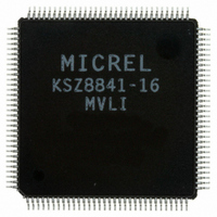
KSZ8841-16MVLI Micrel Inc, KSZ8841-16MVLI Datasheet - Page 27

KSZ8841-16MVLI
Manufacturer Part Number
KSZ8841-16MVLI
Description
Single Ethernet Port + Generic (8, 16-bit) Bus Interface( )
Manufacturer
Micrel Inc
Specifications of KSZ8841-16MVLI
Controller Type
Ethernet Controller, MAC
Interface
Bus
Voltage - Supply
3.1 V ~ 3.5 V
Operating Temperature
-40°C ~ 85°C
Mounting Type
Surface Mount
Package / Case
128-LQFP
Operating Supply Voltage (typ)
3.3V
Operating Temperature Classification
Industrial
Mounting
Surface Mount
Pin Count
128
Lead Free Status / RoHS Status
Lead free / RoHS Compliant
For Use With
576-1632 - BOARD EVALUATION KSZ8841-16MVL
Current - Supply
-
Lead Free Status / RoHS Status
Compliant, Lead free / RoHS Compliant
Other names
576-2114
KSZ8841-16MVLI
KSZ8841-16MVLI
Available stocks
Company
Part Number
Manufacturer
Quantity
Price
Company:
Part Number:
KSZ8841-16MVLI
Manufacturer:
MICREL
Quantity:
441
Micrel, Inc.
KSZ8841-16/32 MQL/MVL/MBL
Functional Description
The KSZ8841M is a single-chip Fast Ethernet MAC controller consisting of a 10/100 physical layer transceiver (PHY), a
MAC, and a Bus Interface Unit (BIU) that controls the KSZ8841M via an 8-bit, 16-bit, or 32-bit host bus interface.
The KSZ8841M is fully compliant to IEEE802.3u standards.
Functional Overview
Power Management
Power down
The KSZ8841M features a port power-down mode. To save power, the user can power-down the port that is not in use by
setting bit 11 in either P1CR4 or P1MBCR register for this port. To bring the port back up, reset bit 11 in these registers.
In addition, there is a full chip power-down mode PWRDN (pin 36). When this pin is pulled-down, the entire chip powers
down. Transitioning this pin from pull-down to pull-up results in a power up and chip reset.
Wake-on-LAN
Wake-up frame events are used to wake the system whenever meaningful data is presented to the system over the
network. Examples of meaningful data include the reception of a Magic Packet, a management request from a remote
administrator, or simply network traffic directly targeted to the local system. In all of these instances, the network device is
pre-programmed by the policy owner or other software with information on how to identify wake frames from other network
traffic.
A wake-up event is a request for hardware and/or software external to the network device to put the system into a
powered state (working).
A wake-up signal is caused by:
1. Detection of a change in the network link state
2. Receipt of a network wake-up frame
3. Receipt of a Magic Packet
There are also other types of wake-up events that are not listed here as manufacturers may choose to implement these in
their own way.
Link Change
Link status wake events are useful to indicate a change in the network’s availability, especially when this change may
impact the level at which the system should re-enter the sleeping state. For example, a change from link off to link on may
1
trigger the system to re-enter sleep at a higher level (D2 versus D3
) so that wake frames can be detected. Conversely, a
transition from link on to link off may trigger the system to re-enter sleep at a deeper level (D3 versus D2) since the
network is not currently available.
Wake-up Packet
Wake-up packets are certain types of packets with specific CRC values that a system recognizes as a ‘wake up’ frame.
The KSZ8841M supports up to four users defined wake-up frames as below:
1. Wake-up frame 0 is defined in registers 0x00-0x0A of Bank 4 and is enabled by bit 0 in wakeup frame control register.
2. Wake-up frame 1 is defined in registers 0x00-0x0A of Bank 5 and is enabled by bit 1 in wakeup frame control register.
3. Wake-up frame 2 is defined in registers 0x00-0x0A of Bank 6 and is enabled by bit 2 in wakeup frame control register.
4. Wake-up frame 4 is defined in registers 0x00-0x0A of Bank 7 and is enabled by bit 3 in wakeup frame control register.
Magic Packet
Magic Packet technology is used to remotely wake up a sleeping or powered off PC on a LAN. This is accomplished by
sending a specific packet of information, called a Magic Packet frame, to a node on the network. When a PC capable of
receiving the specific frame goes to sleep, it enables the Magic Packet RX mode in the LAN controller, and when the LAN
controller receives a Magic Packet frame, it will alert the system to wake up.
1
References to D0, D1, D2, and D3 are power management states defined in a similar fashion to the way they are defined for PCI. For
more information, refer to the PCI specification at www.pcisig.com/specifications/conventional/pcipm1.2.pdf.
October 2007
27
M9999-102207-1.6


