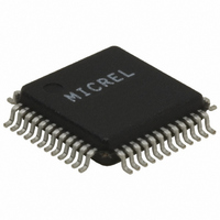
KSZ8851-16MLL Micrel Inc, KSZ8851-16MLL Datasheet - Page 11

KSZ8851-16MLL
Manufacturer Part Number
KSZ8851-16MLL
Description
Single Ethernet Port + Generic (16-bit) Bus Interface( )
Manufacturer
Micrel Inc
Specifications of KSZ8851-16MLL
Controller Type
Ethernet Controller, MAC/PHY
Interface
Bus
Voltage - Supply
1.8V, 2.5V, 3.3V
Operating Temperature
0°C ~ 70°C
Mounting Type
Surface Mount
Package / Case
48-LQFP
Operating Supply Voltage (typ)
3.3V
Operating Temperature Classification
Commercial
Mounting
Surface Mount
Pin Count
48
Lead Free Status / RoHS Status
Lead free / RoHS Compliant
For Use With
576-3292 - BOARD EVALUATION KSZ8851-16MLL
Current - Supply
-
Lead Free Status / RoHS Status
Compliant, Lead free / RoHS Compliant
Other names
576-3252
Available stocks
Company
Part Number
Manufacturer
Quantity
Price
Company:
Part Number:
KSZ8851-16MLL
Manufacturer:
Kendin
Quantity:
1 490
Part Number:
KSZ8851-16MLL
Manufacturer:
MICREL/麦瑞
Quantity:
20 000
Part Number:
KSZ8851-16MLLI
Manufacturer:
MICREL/麦瑞
Quantity:
20 000
Company:
Part Number:
KSZ8851-16MLLI TR
Manufacturer:
Kendin
Quantity:
225
Company:
Part Number:
KSZ8851-16MLLI TR
Manufacturer:
Micrel Inc
Quantity:
10 000
Company:
Part Number:
KSZ8851-16MLLJ
Manufacturer:
Micrel
Quantity:
2 099
Company:
Part Number:
KSZ8851-16MLLTR
Manufacturer:
TIMONTA
Quantity:
23
Company:
Part Number:
KSZ8851-16MLLU
Manufacturer:
Micrel
Quantity:
2 019
Pin Description
August 2009
Micrel, Inc.
Pin Number
10
11
1
2
3
4
5
6
7
8
9
VDD_CO1.8
Pin Name
P1LED1
P1LED0
EED_IO
INTRN
DGND
EESK
WRN
CMD
PME
RDN
Ipu/O
Ipd/O
Ipd/O
Type
Opu
Opu
Opu
Gnd
Ipu
Ipu
Ipd
P
Pin Function
Programmable LED output to indicate port activity/status.
LED is ON when output is LOW; LED is OFF when output is HIGH.
Port 1 LED indicators
Speed = LED On (100BASE-T); LED Off (10BASE-T)
Config Mode: The P1LED1 pull-up/pull-down value is latched as 16/8-bit mode during
power-up / reset. See “Strapping Options” section for details
Power Management Event (default active low): It is asserted (low or high depends on
polarity set in PMECR register) when one of the wake-on-LAN events is detected by
KSZ8851-16MLL. The KSZ8851-16MLL is requesting the system to wake up from low
power mode.
Interrupt: An active low signal to host CPU to indicate an interrupt status bit is set, this pin
need an external 4.7K pull-up resistor.
Read Strobe Not
Asynchronous read strobe, active low to indicate read cycle.
Write Strobe Not
Asynchronous write strobe, active low to indicate write cycle.
Digital ground
1.8V regulator output . This 1.8V output pin provides power to pins 14 (VDD_A1.8) and 29
(VDD_D1.8) for core VDD supply.
If VDD_IO is set for 1.8V then this pin should be left floating, pins 14 (VDD_A1.8) and 29
(VDD_D1.8) will be sourced by the external 1.8V supply that is tied to pins 27, 38 and 46
(VDD_IO) with appropriate filtering.
In/Out Data from/to external EEPROM.
Config Mode: The pull-up/pull-down value is latched as with/without EEPROM during
power-up / reset. See “Strapping Options” section for details
EEPROM Serial Clock
A 4μs (OBCR[1:0]=11 on-chip bus speed @ 25MHz) or 800ns (OBCR[1:0]=00 on-chip
bus speed @ 125MHz) serial output clock cycle to load configuration data from the serial
EEPROM.
Config Mode: The pull-up/pull-down value is latched as big/little endian mode during
power-up / reset. See “Strapping Options” section for details
Command Type
This command input decides the SD[15:0] shared data bus access information.
When command input is low, the access of shared data bus is for data access in 16-bit
mode shared data bus SD[15:0] or in 8-bit mode shared data bus SD[7:0].
When command input is high, the access of shared data bus is for address A[7:2] access
at shared data bus SD[7:2], byte enable BE[3:0] at SD[15:12] and the SD[11:8] is “don’t
care” in 16-bit mode. It is for address A[7:0] access at SD[7:0] in 8-bit mode.
1. Link = LED On; Activity = LED Blink; Link/Act = LED On/Blink;
P1LED1
P1LED0
1
defined as follows:
11
Chip Global Control Register: CGCR bit [9]
LINK/ACT
0 (Default)
100BT
LINK
ACT
1
KSZ8851-16MLL/MLLI
M9999-083109-2.0


