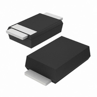
PMEG4010EP,115 NXP Semiconductors, PMEG4010EP,115 Datasheet - Page 3

PMEG4010EP,115
Manufacturer Part Number
PMEG4010EP,115
Description
SCHOTTKY RECT 40V 1.0A SOD-128
Manufacturer
NXP Semiconductors
Series
-r
Datasheet
1.PMEG4010EP115.pdf
(14 pages)
Specifications of PMEG4010EP,115
Package / Case
SOD-128 Flat Leads
Voltage - Forward (vf) (max) @ If
490mV @ 1A
Voltage - Dc Reverse (vr) (max)
40V
Current - Average Rectified (io)
1A
Current - Reverse Leakage @ Vr
50µA @ 40V
Diode Type
Schottky
Speed
Fast Recovery =< 500ns, > 200mA (Io)
Capacitance @ Vr, F
130pF @ 1V, 1MHz
Mounting Type
Surface Mount
Product
Schottky Rectifiers
Peak Reverse Voltage
40 V
Forward Continuous Current
1 A
Max Surge Current
25 A
Configuration
Single
Forward Voltage Drop
430 mV
Maximum Reverse Leakage Current
10 uA
Maximum Power Dissipation
625 mW
Operating Temperature Range
+ 150 C
Mounting Style
SMD/SMT
Reverse Recovery Time (trr)
-
Lead Free Status / RoHS Status
Lead free / RoHS Compliant
Reverse Recovery Time (trr)
-
Lead Free Status / Rohs Status
Lead free / RoHS Compliant
Other names
934061482115
NXP Semiconductors
6. Thermal characteristics
PMEG4010EP_2
Product data sheet
Table 5.
In accordance with the Absolute Maximum Rating System (IEC 60134).
[1]
[2]
[3]
[4]
[5]
Table 6.
[1]
[2]
[3]
[4]
[5]
[6]
Symbol
T
T
T
Symbol
R
R
j
amb
stg
th(j-a)
th(j-sp)
Device mounted on a ceramic PCB, Al
T
Reflow soldering is the only recommended soldering method.
Device mounted on an FR4 PCB, single-sided copper, tin-plated and standard footprint.
Device mounted on an FR4 PCB, single-sided copper, tin-plated, mounting pad for cathode 1 cm
For Schottky barrier diodes thermal runaway has to be considered, as in some applications the reverse
power losses P
Reflow soldering is the only recommended soldering method.
Device mounted on an FR4 PCB, single-sided copper, tin-plated and standard footprint.
Device mounted on an FR4 PCB, single-sided copper, tin-plated, mounting pad for cathode 1 cm
Device mounted on a ceramic PCB, Al
Soldering point of cathode tab.
j
= 25 °C prior to surge.
Limiting values
Thermal characteristics
Parameter
thermal resistance from
junction to ambient
thermal resistance from
junction to solder point
Parameter
junction temperature
ambient temperature
storage temperature
All information provided in this document is subject to legal disclaimers.
R
are a significant part of the total power losses.
Rev. 02 — 15 April 2010
…continued
2
2
O
O
3
3
, standard footprint.
, standard footprint.
Conditions
in free air
Conditions
1 A low V
F
MEGA Schottky barrier rectifier
[1][2]
[3]
[4]
[5]
[6]
PMEG4010EP
Min
-
−55
−65
Min
-
-
-
-
Typ
-
-
-
-
© NXP B.V. 2010. All rights reserved.
Max
150
+150
+150
Max
200
120
60
12
Unit
°C
°C
°C
2
2
.
.
Unit
K/W
K/W
K/W
K/W
3 of 14


